Download
1 / 9
90 likes | 95 Views
Learn about the use of wind tunnel modelling in CFD to determine wind forces on solar trackers and how it helps design the tracker based on actual wind force on the panel area.

E N D
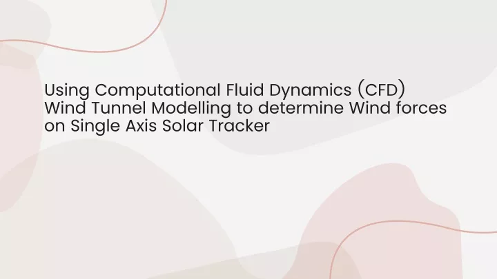
Using Computational Fluid Dynamics (CFD) Wind Tunnel Modelling to determine Wind forces on Single Axis Solar Tracker
Introduction: Wind Tunnel modelling in CFD is a very novel and effective approach to determine wind forces on Solar Trackers. Solar Trackers unlike fixed tilt MMS changes tilt angle based on the sun path for maximum solar incidence. Due to their tilt changing mechanism, Solar Trackers are very susceptible to wind forces. A heavy wind gust can damage the mechanism which is too costly to repair or replace. Inorder to mitigate this as a damage control mechanism, Solar Trackers are programmed to maintain stow position (0 Deg) at high wind times. This CFD study helps to design the tracker based on actual wind force on the panel area.
In this scenario, the solar tracker is positioned at 45˚ tilt as shown in the figure below. The effect of the wind is maximum at this position in any given velocity. This effect is not uniform and has a varied effect at the top and bottom of the module creating an imbalance in loading. The maximum wind speed considered for this particular case is 17 m/s, since above this wind speed the system automatically back-tracks to stow position.
Wind Tunnel Modelling A non-conservative approach in order to estimate the aerodynamic effect on the system has been carried out by coupling CFD and Finite element Structural analysis on different components of the assembly for high wind scenarios. .
The investigation has been carried out by performing CFD wind tunnel analysis to determine the forces on PV modules and support structures in 1:1 scale. The virtual wind tunnel was constructed representing site scenario with naturally existing boundary layer.
Static Pressure on Panels (Pa) . Velocity Vectors – Side view on panel (m/s)
Stress and Deformation plots The below image shows deformation plot of the tracker with reference to the loading calculated from CFD Wind tunnel analysis.
CONCLUSION A combined CFD and FE approach has been undertaken to estimate the wind loads and associated dynamic effects on structural members of the tracking system. The presented approach has been used in the design in order to estimate strength of the structure as a function of wind speed at different orientations. The following conclusions can be made in relation to different orientation of solar tracker and their susceptibility to the effects of wind. 45˚ tilt is the maximum tilting position that the tracking system can make. Vehemently the effect of wind forces is maximum at this position. Under the simulated conditions of 17m/s or 61 KM/hr, it can concluded from the design factor of safety that the solar tracking system can be backtracked to stow position safely.
Graphler Technology Solutions offers finest CFD analysis servicesand also we are well known to provide the bestCAD Conversion Services, Engineering Animation Services etc. Contact us for more information, we are always available to provide assistance whenever you need it.