Download
1 / 5
90 likes | 257 Views
Check the condition of the system after being supplied with the rated system (service) voltage for which it is designed. Also to ensure protection, measuring system for the correct direction.<br><br>

E N D
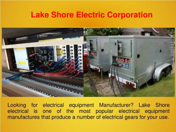
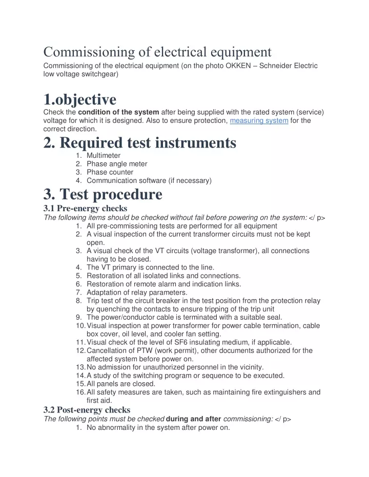
Commissioning of electrical equipment Commissioning of the electrical equipment (on the photo OKKEN – Schneider Electric low voltage switchgear) 1.objective Check the condition of the system after being supplied with the rated system (service) voltage for which it is designed. Also to ensure protection, measuring system for the correct direction. 2. Required test instruments 1. Multimeter 2. Phase angle meter 3. Phase counter 4. Communication software (if necessary) 3. Test procedure 3.1 Pre-energy checks The following items should be checked without fail before powering on the system: </ p> 1. All pre-commissioning tests are performed for all equipment 2. A visual inspection of the current transformer circuits must not be kept open. 3. A visual check of the VT circuits (voltage transformer), all connections having to be closed. 4. The VT primary is connected to the line. 5. Restoration of all isolated links and connections. 6. Restoration of remote alarm and indication links. 7. Adaptation of relay parameters. 8. Trip test of the circuit breaker in the test position from the protection relay by quenching the contacts to ensure tripping of the trip unit 9. The power/conductor cable is terminated with a suitable seal. 10. Visual inspection at power transformer for power cable termination, cable box cover, oil level, and cooler fan setting. 11. Visual check of the level of SF6 insulating medium, if applicable. 12. Cancellation of PTW (work permit), other documents authorized for the affected system before power on. 13. No admission for unauthorized personnel in the vicinity. 14. A study of the switching program or sequence to be executed. 15. All panels are closed. 16. All safety measures are taken, such as maintaining fire extinguishers and first aid. 3.2 Post-energy checks The following points must be checked during and after commissioning: </ p> 1. No abnormality in the system after power on.
2. The voltage measurement must be carried out for all points and found to be normal. 3. Checking the phase sequence for correct rotation. 4. Phase control before paralleling two circuits by the hot contact or the secondary side of the VT. 5. If the circuit is loaded, the secondary current CT of all cores and phases should be measured at an angle to any of the phase voltages. 6. The directional test should be performed for directional protection, such as O / C, E / F directional protection, and distance. This test was explained later. 7. A stability test must be performed for differential protection. 8. If applicable, the automatic voltage monitor load test shall be performed for the transformer. 9. Check the correct readings on the indicator meters. 10. Real-time test for automatic change system, the automatic reclosing system should be performed. commissioning of electrical equipment 3.3 Synchronization and phasing checks Phase controls: Before paralleling two live power supplies, the phasing should be checked even though the source is the same. This could be done in two ways. One method is hot phasing, which is the most reliable method since the verification is carried out on the main one. The voltage difference between the power lines should be monitored by connecting
a heating cable (voltage sensing equipment, designed for system voltage, indicating the presence of voltage) between Rph-Rph, Yph-Yph, Bph-Bph of two feeders respectively in commissioning of electrical equipment Another method is phasing between the VT secondaries, and care should be taken not to make mistakes with the secondary wiring. To ensure the correct connection of the primary and secondary, activate the two VTs by any source and phase out the secondaries. For a correct connection, no voltage difference should be observed during the phase. Now the VTs can be supplied with the power supply of their respective conductor and repeat the phasing between the VT secondaries. If there is no considerable voltage difference between the supply voltages, these are ready to be paralleled. Synchronization control: Before switching to a different source of the same voltage level, in addition to phase control, a synchronization should be performed. The following steps should be followed. 1. Make the correct setting for the timing control relay. 2. Check that the secondary earth of all VTs is at the same point (star or Y phase). 3. Activate both VTs with the same source. 4. Phasing between the VT secondaries, check the synchro control relay is raised continuously and the synchroscope remains at the 12 o’clock position. This ensures that the primary and secondary connections of the VTs are correct. 5. Now power up the VTs with the respective sources commissioning of electrical equipment 6. Check the synchroscope the pointer continues to rotate. This rotation (the incoming voltage vector rotates with respect to the operating voltage) is due to the slip frequency between the sources, i.e. the phase angle between the voltages varying from time to time to time. due to the difference in frequency of the power supplies. 7. If the observed rotation is fast, try to slow it down by increasing or decreasing the speed of the machines. 8. After the rotation is slow, when the voltage phase angle difference decreasing in the setting value, the timing relay detects and drops as soon as the phase angle difference exceeds. 9. It is allowed to compare the sources within this period. 3.4 Directional test This test to check the directional protection/distance relay looks in the desired direction (direction of travel). This could be confirmed by a load test. The principle of the test is that the current and voltage of the load must be simulated in the direction of the trip and that the relay operates. The VT or CT input of the relay must be inverted and observe that the relay is reset.
The procedural method could be the difference with different types of relays. The relay manufacturer’s procedure should be followed for directional control. The following precautions should be taken during the directional test: </ p> The protection is deactivated, i.e., all the deactivated contacts are isolated. Never open the circuit CT of the circuit. At the end of the test, all connections must be reestablished. 3.5 Stability test under load This is the test to confirm the stability of differential protection for a through fault with load current. The following precautions should be taken during the test. The protection is deactivated, i.e., all the deactivated contacts are isolated. Never open the circuit CT of the circuit. At the end of the test, all connections must be reestablished. 3.5.1 Transformer differential protection: Current inputs to the relay of all transformer windings should be measured with a WRT angle, regardless of the phase voltage of VT. The differential current is also measured externally or internally by relay. There should be no differential current (nearly zero) during this test. If the available load on the transformer is not sufficient, this test can be performed by placing two transformers in parallel and holding them at different taps (current will flow between them). 3.5.2 Differential protection of the pilot wire: The CT currents at both ends should be measured with a phase angle. Pilot current should be measured between relays under normal load conditions. The following steps are followed. 1. Isolate the trip and the alarm. 2. Activate the pilot wire relay with the O / C control input activated (if applicable). 3. Measure the input current of the CT relay at both ends in all phases. 4. Measure the pilot current with a normal pilot connection. 5. Connect only the CT of phase “R” to the relay and the short circuit of the other phase and isolate it at both ends. Fig 4.1. 6. Now check the pilot current and verify the relay is stable. 7. Reverse the pilot connection and measure the pilot current. Must the pilot current be reduced and the relay activated for correct operation. 8. It must be repeated for the combination’s “Y”, “B”, “RY”, “YB”, “BR”, “RYB”. 3.5.3 Differential busbar protection: The entire outgoing current must be measured with phase angle. The differential current at the main relay and the voltage on the CT bus must be measured. Under normal load conditions, there should be no differential current and voltage. To get online training in Engineering.
3.6 Checking the count All counters indicate the primary quantity with secondary input quantities. Sometimes it is empowered to verify that the meter reading with the actual inputs verifies polarity, especially in power and energy measurement. For the power meter, the input current and voltage should be measured with an angle.