Download
1 / 7
70 likes | 72 Views
Simerics made a CAE app for the virtual simulation and motor testing, compressors, valves, fluid pumps, and systems. Contact 3hti!

E N D
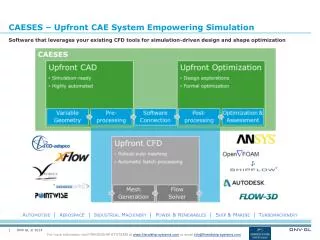
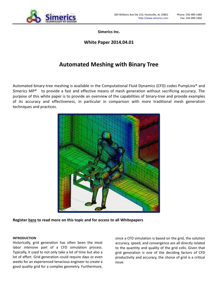
303 Williams Ave Ste 123, Huntsville, AL 35801 http://www.simerics.com Phone: 256-489-1480 Fax: 256-489-1460 Simerics Inc. White Paper 2014.04.01 Automated Meshing with Binary Tree Automated binary-tree meshing is available in the Computational Fluid Dynamics (CFD) codes PumpLinx® and Simerics MP® to provide a fast and effective means of mesh generation without sacrificing accuracy. The purpose of this white paper is to provide an overview of the capabilities of binary-tree and provide examples of its accuracy and effectiveness, in particular in comparison with more traditional mesh generation techniques and practices. Register here to read more on this topic and for access to all Whitepapers INTRODUCTION Historically, grid generation has often been the most labor intensive part of a CFD simulation process. Typically, it used to not only take a lot of time but also a lot of effort. Grid generation could require days or even weeks for an experienced tenacious engineer to create a good quality grid for a complex geometry. Furthermore, since a CFD simulation is based on the grid, the solution accuracy, speed, and convergence are all directly related to the quantity and quality of the grid cells. Given that grid generation is one of the deciding factors of CFD productivity and accuracy, the choice of grid is a critical issue.
Body-fitted binary-tree meshing is a flexible means of generating a highly efficient grid. This type of grid belongs to a family of unstructured body-fitted Cartesian grids. Under this technique, an overlaid cubic grid is refined by factors of two as it approaches regions requiring higher geometric resolution. At a boundary, the grid is cut to conform to the surfaces defining the fluid domain. A simple example is shown in Figure 1, illustrating a binary-tree mesh in a box with a cylinder inside. These capabilities are discussed below. Figure 2. A complex shape, resolved by Binary-Tree mesh. BACKGROUND AND HISTORY The first step in incorporating a physical object into a CFD model is to create a numerical mesh of the geometry that will be used to discretize and solve the governing fluid dynamics equations. Early in the evolution of CFD, these meshes were required to be structured and orthogonal, due to the limitations of the numerical schemes available at the time. This required the simplification of complex shapes into stair-steps at non-aligned or curved boundaries. The next step in the evolution was to overlap cells along these non-aligned surfaces and partially block their volume using cell porosities. Figure 3 shows an example of this approach as applied to a mid eighties model of the flow in the aft-platform seal of the Space Shuttle High Pressure Fuel Pumps [1]. The total number of control volume cells used in the 3-D model was only 8960. While this approach was an improvement over un-modified stair- steps, it was still lacking in terms of resolving boundary layers. Figure 1. Binary-tree mesh around a cylinder. A binary-tree grid is accurate and efficient because: 1. the parent-child tree architecture allows for an expandable data structure with reduced memory storage; 2. binary refinement is optimal for transitioning between different length scales and resolutions; 3. the majority of cells are cubes, which is the optimum cell type in terms of orthogonality, aspect ratio, and skewness thereby reducing the influence of numerical errors and improving speed and accuracy; 4. it can be automated, greatly reducing the set- up time; 5. it can conform to very complex shapes, 6. it can transition continuously from one material to the next, e.g. solid to liquid; 7. it can provide similar accuracy as textrahedral cells with fewer cells, and 8. since the grid is created from a volume, it can tolerate "dirty" CAD surfaces with small cracks and overlaps. a)The domain
A structured mesh, in general, is very efficient and has good accuracy. Another advantage is that it is straightforward to resolve boundary layers in a structured mesh. On the other hand, due to its fully connected grid topology, the structured grid has several drawbacks for complex geometries: 1) Grid generation process can be most tedious and very time consuming for complex geometries; 2) it can result in a highly skewed mesh, thus reducing the solution accuracy and having poor convergence; 3)Since the topology is fully connected, any local refinement, such as for a boundary layer mesh, can potentially create an impractically large total cell counts. Great effort has been made to automate grid generation for structured grids, but there has been only limited success for grid automation. Also, such automation algorithms are not easy to adapt to new designs and typically have trouble including important geometry features such as detailed features. Overall, to create a fully structured mesh for a complete geometry is still a very demanding task. Another popular grid type is the unstructured tetrahedral mesh. Generation of a tetrahedral mesh is much easier and much faster, as compared to a structured mesh. The drawback, however, is that the grid efficiency and grid quality is relatively low. Generally, tetrahedral meshes require several times more cells to get the same accuracy as a hexahedral mesh. In addition, the orthogonality is not very good in most cases. One cannot generate a good boundary layer mesh using only tetrahedral cells. It is also sensitive to the quality of the original geometry surfaces, which are usually directly exported from a CAD package. Another emerging grid type is a special type of polyhedral mesh converted from tetrahedral mesh. By combining a group of neighboring tetrahedral into one polyhedral cell, total cell counts can be reduced significantly while maintaining accuracy. Orthogonality can also be improved during the process. While the cell counts are decreased significantly compared to a tetrahedral grid, unfortunately the number of cell faces are still similar to a tetrahedral mesh. For a control volume based method, in which most computational work is used on face loops, the computational cost for a polyhedral cell can still be much higher than for a structured cell (two times as much or more). Since it is based on tetrahedral cells, the boundary layer still cannot be resolved directly this way, and the requirement for good quality CAD surfaces still holds. b)The mesh Figure 3. Structured “Cell porosity mesh used to model the Space Shuttle HPFTP aft-platform seal [Ref. 1] A significant advancement came with the advent of boundary fitted coordinates that, while structured, conformed to the surfaces. This, followed by the advent of unstructured solvers, has enabled the creation of meshes that conform closely to the geometry and resolve the boundary layers. Since those early methods, several types of grids structures are now used in CFD simulations. A classic approach is a body-fitted structured hexahedra mesh (figure 4.) Figure 4. Body-fitted structured hexahedra mesh [Ref.2 ]
Wang (2007) used 750,000 structured cells for a centrifugal pump simulation with one of the widely used commercial codes [Ref 2]. The CFD program obtained the same level of accuracy compared to experimental data using exactly the same geometry and operation conditions with approximately half the number of cells (390,000 binary-tree cells). Table 1 shows the comparison of the simulation results together with test data for 60%, 100%, and 120% duty flow. Table 1: Comparison of simulation results for a centrifugal pump. Flow rate (m3/h) Experiment Wang & Wang (2007) Present code Experiment Wang & Wang (2007) Present code The structured mesh used in the Wang study is shown above in Figure 4 and the binary tree mesh is shown below in Figure 6. A plot of the comparison data is Table 1 is provided in Figure 7, illustrating the comparable accuracy of the two meshes. 30 50 60 Pressure head (m) 23.50 22.52 21.82 Power (W) 2800 2800 2825 20.54 21.06 20.44 18.34 19.26 18.05 Figure5: Binary tree cell shown in a cutting plane of a centrifugal pump 3540 3710 3638 3810 4010 3847 Figure 5 shows a binary tree mesh on a cutting plane passing through a centrifugal pump. In the regions of high curvature and small details, the grid has been subdivided and cut to conform to the surface. In the boundary layer, the binary tree approach can easily increase the grid density on the surface without excessively increasing the total cell count. The only remaining issue is that it cannot guarantee that the boundary cell is fully aligned with the flow direction. But this drawback is mitigated by the fact that the aspect ratio and skewness of the cells next to the boundaries are of very good quality. Furthermore, to create a structured mesh with fully resolved boundary layer for a complex pump system, a user can end up with a much higher cell count (as compared to a binary tree mesh) since small cell size in boundary layers can propagate to other regions due to grid topology. Also, the aspect ratio and the skewness of the structured cells can increase, which leads to a decrease in overall grid quality, and results in lower accuracy and longer simulation time. Regarding simulation accuracy for integrated values (like pressure head) it has been found that binary tree meshes are as good as well built boundary layer structured grids; especially when dealing with aggressive refinement near the blades and the volute tongue or cutwater. When working with the program, the user selects a set of closed surfaces, typically adjusts one or two resolution parameters, and then clicks to create a high quality grid in a couple of minutes on a regular PC. Thanks to the overall high efficiency of the binary grid, users have demonstrated in many cases that they can use fewer cells to get the same level of accuracy (in comparison to other mesh types). For example, Wang& Figure 6. Binary tree mesh used to compare with Wang and Wang [Ref.2 ]
could go as detailed as 1/1000 of the average length of the object being meshed. Below that limit, the feature is not resolved. In terms of a volume, the default minimum cell value of 0.001 corresponds to a volume scale ~1e-9 of the original geometry volume. This limit can be set even lower, and allows for the resolution of very detailed features. Figure 9 shows an image of an unresolved feature as evident by the uncut cubes at the lower limit of the mesher tolerance. These unresolved cells are referred to as sub-features. Figure 7. Binary tree mesh vs structured results used to compare with Wang and Wang [Ref.2 ] AUTOMATICALLY ADJUSTS TO A RANGE OF SCALES Because the binary tree method refines from large regions to small using factors of two, it is very efficient at transitioning from large scale to small scale. Figure 8 illustrates the automatic resolution of progressively smaller passages in a lubrication circuit. Figure9: Sub-features in a meshed geometry An advantage of the use of sub-features is that they can span cracks and other dirty features in a geometry. Figure 8 shows an example of an under-hood geometry comprised of 11 million stl facets. The geometry was not clean, in that the faces were not fully connected. None-the-less, the PumpLinx binary-tree mesher was able to generate a grid, without any repair, wrapping, or simplification of the geometry. Figure8: Binary tree mesh of a lubrication ciruit DIRTY GEOMETRIES The geometry for the PumpLinx® binary-tree mesher is provided as an stl file. Stl files use triangles to represent surfaces. The PumpLinx binary-tree mesher conforms to these surfaces by successive subdivision of cubic cells, with final cuts to conform to the stl facets. If the stl has defects (i.e. a dirty geometry), or if the scale of the details in the geometry is less than the PumpLinx mesher tolerance limit, the mesher will default to the smallest cube, as defined by a user defined tolerance. In PumpLinx, this minimum limit is defined in terms of a normalized length, such that a minimum of, for example 0.001, would mean that the binary tree refinement Figure9: Model of under-hood flow using binary-tree
CONJUGATE HEAT TRANSFER Another advantage of the binary-tree method is that it produces a continuous mesh across connected volumes, making it well suited for modeling heat transfer through disparate solids and liquids, i.e. conjugate heat transfer. In these cases, care must be taken to insure that there are sufficient cells at the interfaces between volumes to resolve both the thermal and fluid boundary layers. Figure 10 shows an example of a heat exchanger with counter flowing liquids passing through conductive pipes encased in a low conductivity housing. BOUNDARY LAYERS A frequently asked question concerning the PumpLinx binary-tree mesh is whether it can effectively capture boundary layer effects. While the benefits of a well- structured boundary fitted grid are not disputed, the use of special wall functions and cross terms for the multi-faceted boundary layer cells produced by a binary-tree approach produce accurate results for a wide category of engineering problems. As with any method, the user needs to ensure that the cells near a boundary are small enough to resolve the boundary layers. In the binary-tree mesher, this is done by selecting high resolution on the surface itself. This refinement then propagates into the boundary layer. This is especially important for applications where boundary layers are critical, such as in centrifugal pumps. The effectiveness of the binary-tree mesh for such applications has been demonstrated through excellent comparison with experimental results as shown in Figure 11 for a multi-stage axial pump. [Ref 5.] Figure 10:Conjugate heat transfer simulation of a heat exchanger, using a binary-tree mesh SPEED Because the binary tree mesh overlays the geometry and automatically refines, it is significantly faster than other techniques in creating a mesh. As an example, the time required to genertate the 46 million cell mesh for the model in Figure 9 above was 2.5 hours on a dual quad core Xeon 5550 (2.67 Ghz) PC with 48 GB memory. (The time to run the simulation was only 18 hours on the same computer.) Figure 11: PumpLinx predictions vs Experiment for an HMS mixed flow pump
Efficiently adjusts to a range of length scales Can handle “dirty” geomeries Has been shown to be accurate for a range of application, including capturing boundary layers "PumpLinx for me has surpassed all expectations: 3D model preparation - 2 hours maximum, 1 hour on average. No problems with mesh creation - always created and there are no errors in the calculations because of the quality of the grid. Calculation of the first characteristic point is no more than 10-30 minutes, which is 10-30 times faster than our main program. Accuracy of the calculation for the pressure and for the efficiency in the range of 1% to 3% max (in the operating range of feeds, and for one pump and throughout the feature). To sum up the total: a great program for the engineer;quick and easy; Overall evaluation of 9 out of 10 (with 10 being a perfect virtual [Score])" REFERENCES 1.Lowry, S. and Keeton, L.W. , “Space Shuttle Main Engine High Pressure Fuel Pump Aft Platform Seal Cavity Flow Analysis,” NASA Technical Paper, 2685, January 1987. 2.Wang and Wang, ““Performance prediction of centrifugal pump based on the method of numerical simulation,” Fluid Machinery, vol. 35, pp. 9-13. 3.Ding, H., Visser, F.C., Jiang, Y. and Furmanczyk, M. 2011 “Demonstration and validation of a 3D CFD simulation tool predicting pump performance and cavitation for industrial applications", J. Fluids Eng. – Trans ASME, 133(1), 011101. 4.Ding, H., Visser, F.C., and Jiang, Y. 2012 “A practical approach to speed up NPSHR Predictions of Centrigfugal Pumps using CFD Cavitation Models ", FEDSM2012- 72282, Proceedings of FEDSM2012, 2012 ASME Fluids Engineering Division Summer Meeting. 5."Cost cutting with pump performance prediction," published in the July/August 2013 edition of World Pumps (www.worldpumps.com ). - Lead Engineer at HMS Group Russia SUMMARY The binary-tree meshing method, as implemented in PumpLinx, is an automated mesh that Is user-friendly, robust and fast with regard to mesh generation Provides efficient use of the cell count and storage Can be used for disparate materials (e.g. conjugate heat transfer through liquids and solids)