Download
1 / 41
410 likes | 889 Views
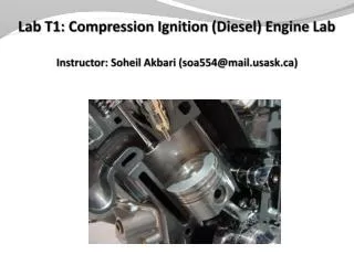
Introduction. Initial CI engines were large and slow.Heavy distillate petroleum was forced into the cylinder using compressed air.Robert Bosch began producing injection systems in 1927. . CI vs. SI Engines. SI engines draw fuel and air into the cylinder.Fuel must be injected into the cylinder at the desired time of combustion in CI engines.Air intake is throttled to the SI engine -- no throttling in CI engines.Compression ratios must be high enough to cause auto-ignition in CI engines.Upp9441

E N D
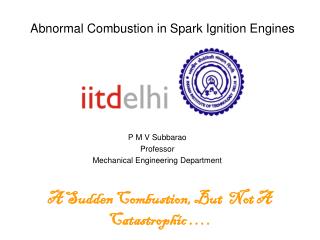
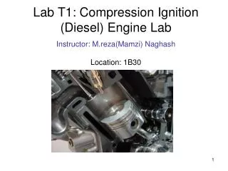
1. Chapter 7: Compression Ignition Engines BAE 599 - Lecture 7
3. CI vs. SI Engines SI engines draw fuel and air into the cylinder.
Fuel must be injected into the cylinder at the desired time of combustion in CI engines.
Air intake is throttled to the SI engine -- no throttling in CI engines.
Compression ratios must be high enough to cause auto-ignition in CI engines.
Upper compression ratio in SI engines is limited by the auto-ignition temperature.
4. CI vs. SI Engines Flame front in SI engines smooth and controlled.
CI combustion is rapid and uncontrolled at the beginning.
5. Table 7.1: Comparison of SI and CI Engines
6. Fig. 7.1: Typical Brake Thermal Efficiencies of CI and SI Engines
7. Fig. 7.2: CI Combustion Chamber Design
8. Injection Approaches Figures b, c and d are �indirect injection (IDI)� methods.
Figure a is �direct injection (DI)�.
IDI engines are quieter that DI engines.
Less stress in IDI engines translates to smaller engines � automotive applications.
9. Pre-Combustion Chambers Fig. 7.2b is a pre-combustion chamber where its volume is 20-30% of the total clearance volume.
Temperature of PC is 600-750 C � much hotter than the remainder of the chamber.
Throat causes turbulence which add to mixing during combustion process.
10. Swirl Chamber Fig. 7.2c illustrates a �swirl chamber� which is between 50 and 90% of the clearance volume.
Counterclockwise flow creates high levels of turbulence.
Swirl chambers cause extremely complete combustion with low levels of NOx, smoke and unburned hydrocarbons in the exhaust.
11. Energy Cell Fig. 7.2d depicts an �energy cell� sized so as to contain approximately 5 to 15% of the total clearance volume.
Combustion is initiated in the main chamber, forcing approximately 60% of the fuel into the �energy cell.�
Combustion process last longer � indicate thermal efficiency is lower
12. Direct Injection Fuel injected into the primary combustion chamber with �direct injection� (DI).
DI engines tend to be 8-10% more efficient than IDI engines.
Primary engine in the truck, bus, construction and agriculture industries.
13. Fig. 7.3: Air Swirl in DI Engine
14. Swirl Ratio DI engines are designed so that the adequate mixing of air and fuel is enhanced by a swirling action within the combustion chamber.
Engines are designed with a specific swirl ratio � typically 2.5 (swirling rotation within cylinder versus engine speed).
15. Fig. 7.4 Conventional Fuel Systems
16. Fuel Flow Tank to low pressure fuel pump.
Fuel pump through filter.
Filter to injection pump.
High pressure flow from injection pump to injectors.
Fuel injected into cylinder, or
Low pressure leakage from top of injector is returned to tank.
17. Fig. 7.5: In-Line Injection Pumps
18. Injection Pump Operation Rack is advanced to rotate scroll valves.
Scroll position corresponds to amount of fuel to be metered to the injector.
Plunger is actuated by cam underneath that is timed to individual cylinders.
To stop engine rack is closed � covering port A.
Fuel to injector metered through port A�.
19. Delivery Valve Action If pressure of injection lines is permitted to fall to zero between injections, compressibility of fuel would cause system injections pressures to rise too slowly.
Slow pressure response results in dribbling at the injector � resulting in poor engine performance.
20. Pressure Changes in Injection Lines The following relationship can be utilized to investigate relationship between line volume and pressure changes,
where Vt is the total line volume, DV is the change in volume, Dp is the change in line pressure, and be is the effective bulk modulus of the line.
21. Effective Bulk Modulus The effective system bulk modulus is determined by looking at the combined effect of each entity,
where be is the effective bulk modulus of the line, bf is the bulk modulus of the fuel, bc is the bulk modulus of the steel line, and bg is the bulk modulus of the entrained air.
22. Typical Bulk Modulus Values bf is 1,860 MPa
bc is E/2.5 or 208,205 MPa
ba is 1.4p or 20 MPa
be is 19.8 MPa
Effective bulk modulus is dominated by the bulk modulus of air.
23. Fig. 7.6: Distributing Injection Pump
24. Distributing Injection Pump Cheaper to manufacture � fewer parts.
Vane-type charge pump with pressure regulation supplies fuel to the rotary metering valve.
Metering valve limits the flow of fuel into the main pump (just enough to support the load on the engine), forcing the pump plungers apart.
The rollers at the cam force the plungers into the center, the in-flow ports are blocked, and the fuel is forced to flow through the rotor to the distributor.
25. Fig. 7.7: Cam Advance Mechanism
26. Cam Advance Mechanism When fuel pressure declines � reduced engine speed � the spring in the piston expands rotating the cam and retarding the timing.
At higher engine speeds increased fuel pressure compresses the spring rotating the cam to advance the timing.
27. Fig. 7.8: Conventional Injection Nozzles
28. Fig. 7.9: Cutaway of Conventional Injection Nozzle
29. Fig. 7.10: Nozzle Pop Tester
30. Fig. 7.11: Mechanically Controlled Unit Injectors
31. Unit Injectors One for each cylinder.
Actuated by an extra lobe on the camshaft.
Uses scroll valve � similar to in-line injection pumps.
Linkage required for changing scroll valve position and advancing injection.
32. Fig. 7.12: Electronic Controlled Unit Injector
33. Fig. 7.13: Hydraulic Electronic Controlled Unit Injector (HEUI)
34. Fig. 7.15: HEUI Waveforms
35. Fig. 7.16: Common Rail Electronic Injection (CREI)
36. CREI Manifold pressures on 140 MPa.
ECU regulates pump delivery to maintain system pressure to within 5 MPa.
ECU energizes solenoid at injector to begin injection.
Small pilot injection is provided in advance of main injection.
37. Fig. 7.17: CREI Injector
38. Fig. 7.18: CREI Injection Wave Forms
39. Fig. 7.19: Causes of Diesel Smoke
40. Cols Starting of CI Engines Engines will typically start at 5 to 10 C and above without starting aids.
Sometimes two batteries are connected in series for 24 VDC starting circuits. Most new startesr are 12 VDC.
Glow plugs are added to the pre-combustion chambers on IDI engines.
Ether can be used as a starting aid in DI engines.
Intake manifold heaters are used in DI engines to heat incoming air.
Block heaters are a viable option for starting engines during extended cold periods.
41. Homework Set No. 6 Do the odd problems at the end of Chapter 7 for next Tuesday.