Download
1 / 5
50 likes | 60 Views
ER Publication,<br> IJETR, IJMCTR,<br> Journals,<br> International Journals,<br> High Impact Journals, <br>Monthly Journal, <br>Good quality Journals,<br> Research, <br>Research Papers,<br> Research Article, <br>Free Journals, Open access Journals, <br>erpublication.org,<br> Engineering Journal,<br> Science Journals,

E N D
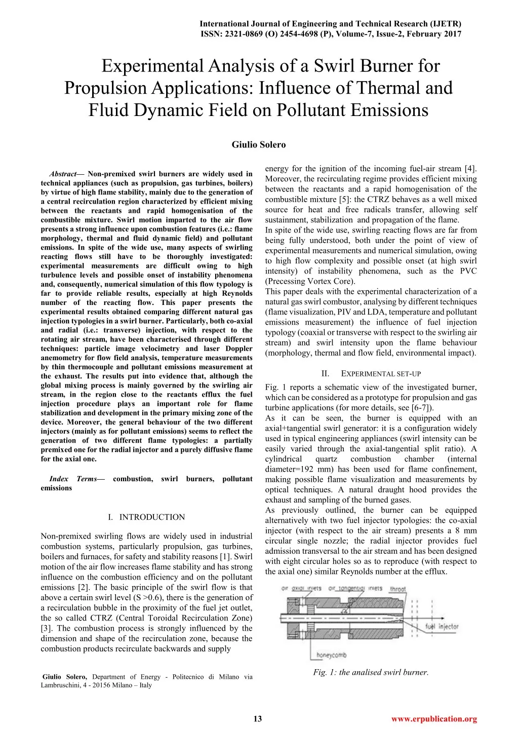
International Journal of Engineering and Technical Research (IJETR) ISSN: 2321-0869 (O) 2454-4698 (P), Volume-7, Issue-2, February 2017 Experimental Analysis of a Swirl Burner for Propulsion Applications: Influence of Thermal and Fluid Dynamic Field on Pollutant Emissions Giulio Solero energy for the ignition of the incoming fuel-air stream [4]. Moreover, the recirculating regime provides efficient mixing between the reactants and a rapid homogenisation of the combustible mixture [5]: the CTRZ behaves as a well mixed source for heat and free radicals transfer, allowing self sustainment, stabilization and propagation of the flame. In spite of the wide use, swirling reacting flows are far from being fully understood, both under the point of view of experimental measurements and numerical simulation, owing to high flow complexity and possible onset (at high swirl intensity) of instability phenomena, such as the PVC (Precessing Vortex Core). This paper deals with the experimental characterization of a natural gas swirl combustor, analysing by different techniques (flame visualization, PIV and LDA, temperature and pollutant emissions measurement) the influence of fuel injection typology (coaxial or transverse with respect to the swirling air stream) and swirl intensity upon the flame behaviour (morphology, thermal and flow field, environmental impact). Abstract— Non-premixed swirl burners are widely used in technical appliances (such as propulsion, gas turbines, boilers) by virtue of high flame stability, mainly due to the generation of a central recirculation region characterized by efficient mixing between the reactants and rapid homogenisation of the combustible mixture. Swirl motion imparted to the air flow presents a strong influence upon combustion features (i.e.: flame morphology, thermal and fluid dynamic field) and pollutant emissions. In spite of the wide use, many aspects of swirling reacting flows still have to be thoroughly investigated: experimental measurements are difficult owing to high turbulence levels and possible onset of instability phenomena and, consequently, numerical simulation of this flow typology is far to provide reliable results, especially at high Reynolds number of the reacting flow. This paper presents the experimental results obtained comparing different natural gas injection typologies in a swirl burner. Particularly, both co-axial and radial (i.e.: transverse) injection, with respect to the rotating air stream, have been characterised through different techniques: particle image velocimetry and laser Doppler anemometry for flow field analysis, temperature measurements by thin thermocouple and pollutant emissions measurement at the exhaust. The results put into evidence that, although the global mixing process is mainly governed by the swirling air stream, in the region close to the reactants efflux the fuel injection procedure plays an important role for flame stabilization and development in the primary mixing zone of the device. Moreover, the general behaviour of the two different injectors (mainly as for pollutant emissions) seems to reflect the generation of two different flame typologies: a partially premixed one for the radial injector and a purely diffusive flame for the axial one. II. EXPERIMENTAL SET-UP Fig. 1 reports a schematic view of the investigated burner, which can be considered as a prototype for propulsion and gas turbine applications (for more details, see [6-7]). As it can be seen, the burner is equipped with an axial+tangential swirl generator: it is a configuration widely used in typical engineering appliances (swirl intensity can be easily varied through the axial-tangential split ratio). A cylindrical quartz combustion diameter=192 mm) has been used for flame confinement, making possible flame visualization and measurements by optical techniques. A natural draught hood provides the exhaust and sampling of the burned gases. As previously outlined, the burner can be equipped alternatively with two fuel injector typologies: the co-axial injector (with respect to the air stream) presents a 8 mm circular single nozzle; the radial injector provides fuel admission transversal to the air stream and has been designed with eight circular holes so as to reproduce (with respect to the axial one) similar Reynolds number at the efflux. chamber (internal Index Terms— emissions combustion, swirl burners, pollutant I. INTRODUCTION Non-premixed swirling flows are widely used in industrial combustion systems, particularly propulsion, gas turbines, boilers and furnaces, for safety and stability reasons [1]. Swirl motion of the air flow increases flame stability and has strong influence on the combustion efficiency and on the pollutant emissions [2]. The basic principle of the swirl flow is that above a certain swirl level (S >0.6), there is the generation of a recirculation bubble in the proximity of the fuel jet outlet, the so called CTRZ (Central Toroidal Recirculation Zone) [3]. The combustion process is strongly influenced by the dimension and shape of the recirculation zone, because the combustion products recirculate backwards and supply Fig. 1: the analised swirl burner. Giulio Solero, Department of Energy - Politecnico di Milano via Lambruschini, 4 - 20156 Milano – Italy 13 www.erpublication.org
Experimental Analysis of a Swirl Burner for Propulsion Applications: Influence of Thermal and Fluid Dynamic Field on Pollutant Emissions Tab. 1 reports the nominal operating conditions used for the experimental measurements described in this paper. Air flow rate [g/s] Reynolds number of air jet Natural gas flow rate [g/s] Reynolds number of natural gas jet Input thermal power [kW] Air swirl number S Fuel/Air Momentum ratio MR Fuel/Air Equivalence ratio Tab.1: nominal operating conditions of the burner. 8.8 20700 0.35 5600 17 0.82 0.92 0.69 Fig. 2a: typical image of the flame for axial injector. Owing to the high complexity of the flow inside the combustion chamber (due to the high swirl intensity imparted to the air stream), the experimental characterization has been carried out through different techniques. Flow field measurements in reacting conditions have been performed both by laser Doppler anemometry and particle image velocimetry [8]. In this case, a double seeding has been used to have the complete characterization of the flow field. Particularly: Silicon oil droplets (mean diameter=1 dispersed in the fuel flow, to reproduce the central jet penetration (in the case of axial injector) and obtain velocity measurements referred to the “cold” natural gas jet interacting with the recirculating central bubble; Alumina particles (mean diameter=5 added in the corner region at the base of the combustion chamber, reproducing mainly the recirculating flow of already burned gases. Fig. 2b: typical image of the flame for radial injector. Mean temperature was measured using a Pt/Pt-13% Rh bare wire thermocouple with 0.3 mm diameter bead. The amplified signals were sampled at a 500 Hz sampling frequency and the mean value was based on 5000 instantaneous data. A correction was made for the radiation error, following [9] and using the measured velocity values for the evaluation of convective heat transfer coefficient. Finally, burned gases have been sampled for analysis of the pollutant emissions (chemiluminescence for NOxand infrared analysis for CO). As for the macroscopic flow field, the difference between the two injectors is visible in Fig. 3a, b, which reports the 2-D flow field measured by PIV averaging 200 double-exposed images (for the radial injector, the investigated plane includes two injection nozzles). For both injectors, it is clearly noticeable the generation of the recirculation bubble due to swirl effect imparted to the air stream. However, the use of the radial injector, obviously, avoids the possible interaction of the central jet with the formation of the recirculating region, which is generated just downstream the efflux, very close to the burner head, contributing to flame stability and reactants mixing (with already burned gases too) enhancement with respect to axial injection. In fact, fuel jets seem to be soon entrained in the transverse air stream, inducing rapid mixing. For the axial injector, the interaction between the central fuel jet and the recirculating central region has been deepened through LDA. Velocity measurements for the axial component along the burner axis and close to the region of interaction gave rise to bi-modal distributions (see Fig. 4), connected to the simultaneous presence of the positive (fuel jet) and negative (recirculating gases) velocity regime. This puts into evidence the possibility of sporadic penetration of the fuel jet inside the bubble, a phenomenon originating the luminous zone visible in Fig. 2a. In Fig. 4 the progressive appearance of the central recirculation region and its interaction with the central fuel jet is clearly visible. III. RESULTS AND DISCUSSION 3.1 – Flame morphology and flow field Fig. 2 a, b reports the image of the flame for the different injection typologies (nominal operating conditions reported in Tab. 1). It can be observed the typical calyx shaped flame, due to swirl, and, for the axial injector, the formation of a central luminous region connected to fuel penetration inside the recirculating bubble, generating a fuel rich zone and giving rise to soot formation. This phenomenon, anyway sporadic for axial injector, is always absent for the radial one. The higher stability and compactness of the flame in the case of radial injection is proved by the results obtained by CH* emission spectroscopy from the flame front, not reported here [10], putting into evidence that the reaction zone (identified by the peak of CH* emission intensity) for radial injector is closer and more concentrated at the burner head, with an initial steeper gradient. 14 www.erpublication.org
International Journal of Engineering and Technical Research (IJETR) ISSN: 2321-0869 (O) 2454-4698 (P), Volume-7, Issue-2, February 2017 1500 1400 1300 1200 1100 1000 900 T [°C] 800 700 600 H 3 mm H 18 mm H 33 mm H 63 mm H 93 mm H 123 mm 500 400 300 200 100 0 0 1 2 3 4 5 R/Reff Fig. 3a: Flow field for axial injector. Fig. 5: radial temperature semi-profiles measured for axial injector. 1300 1200 1100 1000 900 Temperatura [C] 800 700 600 500 H 3 mm H 18 mm H 33 mm H 63 mm H 93 mm H 123 mm 400 300 200 100 0 Fig. 3b: Flow field for radial injector. 0 1 2 3 4 5 R/Reff Fig. 6: radial temperature semi-profiles measured for radial injector. Close to the efflux, the axial injector presents a central relatively “cold” region which can be attributed to the natural gas jet, separated from the parallel “cold” air stream by a relatively hot zone that can be attributed to incipient formation of the recirculation region and development of combustion reactions. At the contrary, for the radial injector the central region is characterised by high temperature levels due to recirculation of hot already burned gases till the burner head (see Fig. 3b); air stream outflowing is clearly visible with low temperature levels (similar for the two injection typologies). At the periphery (i.e., R/Reff>1) in both cases there is a region characterised by a quasi uniform temperature value (about 800-1000 °C) which is connected to the formation of a corner recirculation zone visible also in Figgs. 3a, b. This corner reverse flow, already observed in a similar burner [11], is induced by the air stream radial expansion and the wall confinement: the high temperatures measured in this zone indicate the presence of a large amount of already burned gases that are entrained by the reactant flow. MR=0.92, =0.69, h/d=3.25. MR=0.92, =0.69, h/d=3.5. MR=0.92, =0.69, h/d=3.75. MR=0.92, =0.69, h/d=4. Fig. 4: velocity histograms from LDA measurements (axial injector) at progressive increasing distance from the efflux. 3.2 – Thermal field The different behaviour of the two injectors, especially close to the reactants efflux, is evident also in the temperature measurements. Figgs. 5, 6 report the comparison of radial temperature semi-profiles, at progressive increasing distance H from the efflux, for axial and radial injector respectively. Figgs. 7, 8 present the super-imposition of mean temperature and mean axial velocity profiles at a distance H=3 mm from the efflux, confirming the correspondence of thermal and flow field, previously described. 15 www.erpublication.org
Experimental Analysis of a Swirl Burner for Propulsion Applications: Influence of Thermal and Fluid Dynamic Field on Pollutant Emissions However, the radial injector gives rise to more uniform profiles and differences up to 150 °C are present probably connected to a distinct development of combustion reactions and local heat release (see Figgs. 2a, b and 3). 900 30 800 25 700 20 Axial Vel. [m/s] Temperature [°C] 600 15 500 3.3 – Pollutant emissions Finally, pollutant emissions (CO and NOx) at the exhaust have been measured for the two injectors in different operating conditions, that is varying equivalence ratio, and for two values of air swirl number: the nominal one (0.82) and a lower value (0.65). Swirl number variation is possible modifying the axial-tangential split ratio in the swirl generator. Variation of the equivalence ratio has been obtained changing fuel flow rate and, consequently, input thermal power and momentum ratio, but maintaining constant the air flow rate and, as a consequence, the Reynolds number and the macroscopic fluid dynamic of the flow. Results are reported in Figgs. 11, 12, 13 and 14. As it can be seen, the graphs report the blow-off limit for the lean flame and are also useful to define the possible operability range of the burner. Blow-off limit in lean conditions is mainly dictated by swirl intensity rather than injection procedure: in this case, the lower swirl number allows the extension of blow-off limit towards leaner conditions, to the detriment of CO emissions which become very high. Probably, the higher value of swirl number can enhance flame local stretching inducing instability phenomena (such as the PVC, Precessing Vortex Core) clearly observed in isothermal conditions. The radial injector presents lower NOx emissions (up to 50% in lean condition) with respect to the axial one and its behaviour under the point of view of pollutant emissions is strictly dependent from equivalence ratio rather than swirl number (although enhancement of swirl intensity gives rise to lower emission levels). In fact, for the radial injector, a steep increase of NOx emissions has been pointed out approaching stoichiometric flames. At the same time, a relevant increase of CO formation is noticeable in lean conditions. At the contrary, especially for high swirl number, the axial injector seems quite insensitive to equivalence ratio and a slight decrease in NOx emissions can be revealed close to stoichiometric flame, associated with increase of CO emission (probably connected to strong penetration of central fuel jet with subsequent possible mixing deficiency). The general behaviour of the two different injectors as for pollutant emissions seems to reflect the generation of two different flame typologies: a partially premixed one for the radial injector and a purely diffusive flame for the axial one. 10 400 5 300 0 200 Temperature Axial velocity -5 100 0 -10 0 1 2 3 4 5 R/Reff Fig. 7: super-imposition of mean temperature and axial velocity profile at H=3 mm for the axial injector. 1000 30 25 800 20 Axial Vel. [m/s] Temperature [°C] 15 600 10 400 5 0 Temperature Axial velocity 200 -5 0 -10 0 1 2 3 4 5 R/Reff Fig. 8: super-imposition of mean temperature and axial velocity profile at H=3 mm for the radial injector. Figgs. 9, 10 report the comparison of temperature-axial velocity trend along the burner axis, for both injectors. 15,0 1200 12,5 10,0 1000 7,5 Axial Vel. [m/s] 5,0 Temperature [°C] 800 2,5 0,0 600 -2,5 -5,0 400 -7,5 -10,0 200 Temperature Axial Velocity -12,5 0 -15,0 0 10 20 30 40 50 60 70 80 90 100 110 120 130 H [mm] Fig. 9: temperature and axial velocity behaviour along the burner axis, for axial injector. 15,0 1200 12,5 Radial Axial 10,0 SWIRL 0.65 110 1000 7,5 Axial Vel. [m/s] 5,0 100 Temperature [°C] 800 2,5 90 0,0 blow-off 600 mg NO2/Nm3 3% O2 -2,5 80 -5,0 400 70 -7,5 60 -10,0 200 Temperature Axial Velocity -12,5 50 0 -15,0 0 10 20 30 40 50 60 70 80 90 100 110 120 130 40 H [mm] blow-off 30 Fig. 10: temperature and axial velocity behaviour along the burner axis, for radial injector. At increasing distance from the efflux the temperature profiles become more uniform (full development of combustion reactions): the profile trend is similar for the two injectors. 20 Equiv. Ratio 0,3 12 0,4 0,5 15 0,6 0,7 20 0,8 0,9 25.2 1,0 Input Power[kW] 0.32 0.47 MR 0.9 1.41 Fig. 11: comparison of NOx emissions at swirl number=0.65. 16 www.erpublication.org
International Journal of Engineering and Technical Research (IJETR) ISSN: 2321-0869 (O) 2454-4698 (P), Volume-7, Issue-2, February 2017 fuel penetration and formation of a sooting luminous region, a phenomenon obviously absent in the case of radial injection. The difference between the two injection procedures is clearly noticeable also as for pollutant emissions at the exhaust. In fact, the radial injector presents lower emission levels with respect to axial one and seems to give rise to a flame quite similar to a partially premixed one, with positive effects on development of new burners characterised by low environmental impact. Radial Axial blow-off SWIRL 0.65 12000 10000 mg/Nm3 CO 3% O2 8000 6000 4000 blow-off 2000 Moreover, the obtained results can constitute a representative data set for validation of numerical codes and turbulence models in the field of reacting turbulent flows. 0 Equiv. Ratio 0,3 12 0,4 0,5 15 0,6 0,7 20 0,8 0,9 25.2 1,0 Input Power [kW] 0.47 0.9 0.32 MR 1.41 Fig. 12: comparison of CO emissions at swirl number=0.65. REFERENCES Radial Axial 110 SWIRL 0.82 [1] A.K. Gupta, D.G. Lilley, N. Syred: “Swirl flows”, Abacus Press, Tunbridge Wells, 1984 [2] T.C. Claypole, N. Syred: “The effect of swirl burner aerodynamics on NOx formation”, 18thSymposium (International) on Combustion, The Combustion Institute, 1981, p. 81 [3] R. Hillemans, B. Lenze, W. Leuckel: “Flame stabilization and turbulent exchange in strongly swirling natural gas flames”, 21stSymposium (International) on Combustion, The Combustion Institute, 1986, p. 1445 [4] V. Tangirala, J.F. Driscoll: “Temperatures within non-premixed flames: effects of rapid mixing due to swirl”, Combustion Science and Technology, 60, (1988), 143 [5] R.H. Chen, J.F. Driscoll: “The role of recirculation vortex in improving fuel-air mixing within swirling flames”, 22ndSymposium (International) on Combustion, The Combustion Institute, 1988, p. 531 [6] G. Solero, A. Coghe, G. Scribano: “Influence of natural gas injection procedure in a swirl burner”, Joint Meeting of the Greek and Italian Sections of The Combustion Institute, Corfu, June 17-19 2004 [7] Olivani A., Solero G., Cozzi F., Coghe A., (2007): “Near field flow structure of isothermal swirling flows and reacting non-premixed swirling flames”, Experimental Thermal and Fluid Science, vol. 31, 427-436 [8] Araneo L., Coghe A., Cozzi F., Olivani A., Solero G., (2008): “Natural gas burners for domestic and industrial appliances: application of the particle image velocimetry (PIV) technique”, in: Schroder A., Willert C.E., Particle Image Velocimetry, Topics in Appl. Physics, pp. 245-257, Heidelberg Springer Verlag [9] T.V. Morgan: “Thermal behaviour of electrical conductors”, John Wiley and Sons, New York, 1991 [10] G. Solero, A. Olivani, F. Cozzi, A. Coghe (2005): “Experimental analysis of fuel injection procedure in a natural gas swirling flame”, European Combustion Symposium, 2005 [11] A. Coghe, G. Solero, G. Scribano (2004): “Recirculation phenomena in a natural gas swirl combustor”, Experimental Thermal and Fluid Science, vol. 28, (2004), 709-714 100 90 80 mg NO2/Nm3 3% O2 70 60 blow-off 50 40 30 blow-off 20 Equiv. Ratio 0,3 12 0,4 0,5 15 0,6 0,7 20 0,8 0,9 25.2 1,0 Input Power[kW] MR 0.32 0.47 0.9 1.41 Fig. 13: comparison of NOx emissions at swirl number=0.82. Radial Axial 2500 SWIRL 0.82 2000 mg/Nm3 CO 3% O2 1500 1000 500 blow-off blow-off 0 Equiv. Ratio 0,3 12 0,4 0,5 15 0,6 0,7 20 0,8 0,9 25.2 1,0 Input Power [kW] 0.47 0.9 0.32 MR 1.41 Fig. 14: comparison of CO emissions at swirl number=0.82. IV. MAINCONCLUSIONS The experimental analysis through different techniques of a natural gas burner varying the gas injection procedure (axial or transverse with respect to air stream) put into evidence how this procedure plays an important role in flame stabilization and development close to the reactants efflux, being the global mixing process governed by swirl effect imparted to the air. Particularly, it has been deepened the knowledge about the possible interaction (for axial injection) between the central fuel jet and the recirculating bubble, which can induce 17 www.erpublication.org