Download
1 / 76
910 likes | 1.97k Views
FINAL CONTROL ELEMENT. FINAL CONTROL ELEMENT. The final control element adjust the amount of energy/mass goes into or out from process as commanded by the controller The common energy source of final control elements are: Electric Pneumatic Hydraulic. ELECTRIC FINAL CONTROL ELEMENT.

E N D
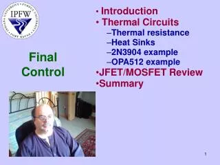
FINAL CONTROL ELEMENT • The final control element adjust the amount of energy/mass goes into or out from process as commanded by the controller • The common energy source of final control elements are: • Electric • Pneumatic • Hydraulic
ELECTRIC FINAL CONTROL ELEMENT • Electric current/voltage • Solenoid • Stepping Motor • DC Motor • AC Motor
CHANGING CURRENT/VOLTAGE • Current or voltage can be easily changed to adjust the flow of energy goes into the process e.g. in heating process or in speed control • Heater elements are often used as device to keep the temperature above the ambient temperature. Energy supplied by the heater element is W = i2rt (i=current, r=resistance, t=time) • Motor is often used as device to control the speed
CHANGING CURRENT/VOLTAGE • Using • Potentiometer • Amplifier • Ward Leonard system • Switch (on-off action)
Changing Current/VoltageUsing Rheostat I = V/(R1+R2) Power at rheostat P1 =I2R1 Power at heater P2 =I2R2 Disadvantage loss of power at rheostat Rheostat Heater R1 V R2 I
Changing Current/VoltageUsing Amplifier Potentiometer V+ Heater amplifier R1 V R2 V− Disadvantage loss of power at potentiometer (very small) and at Amplifier
Changing Current/VoltageUsing Ward Leonard System • Introduced by Harry Ward Leonard in 1891 • Use a motor to rotate a generator at constant speed • The output of generator voltage is adjusted by changing the excitation voltage • Small change in excitation voltage cause large change in generator voltage • Able to produce wide range of voltage (0 to 3000V) • Ward Leonard system is popular system to control the speed of big DC motor until 1980’s • Now a days semi conductors switches replaces this system
Changing Current/VoltageUsing Ward Leonard System excitation voltage MOTOR GENERATOR
Changing Current/VoltageUsing Switch • The switch is closed and opened repeatedly • No power loss at switch Switch closed VL Switch V LOAD V VL t Switch opened
DUTY CYCLE VL V • T is period time typical in millisecond order (fix) • Ton is switch on time (adjustable) • Toff is switch off time Duty Cycle is: (Ton/T) 100% t Ton Toff T • Of course we can not use mechanical switches to carry on this task, electronic switches to be used instead. • E.g. Transistor, Thyristor, or IGBT • This methods is often called as Pulse Width Modulation (PWM)
SOLENOID • When the coil is energized the core will be pulled in core coil core coil SOLENOID
SOLENOID • When the coil is energized the core will be pulled in V SIMULATE
SOLENOID • When the coil is energized the core will be pulled in V SIMULATE
SOLENOID Rotary solenoid Tubular solenoid Open frame solenoid
Solenoid Usage • pushing buttons, • hitting keys on a piano, • Open closed Valve, • Heavy duty contactor • jumping robots • etc
STEPPING MOTOR The top electromagnet (1) is turned off, and the right electromagnet (2) is energized, pulling the nearest teeth slightly to the right. This results in a rotation of 3.6° in this example. The top electromagnet (1) is turned on, attracting the nearest teeth of a gear-shaped iron rotor. With the teeth aligned to electromagnet 1, they will be slightly offset from electromagnet
STEPPING MOTOR The left electromagnet (4) is enabled, rotating again by 3.6°. The bottom electromagnet (3) is energized; another 3.6° rotation occurs. When the top electromagnet (1) is again enabled, the teeth in the sprocket will have rotated by one tooth position; since there are 25 teeth, it will take 100 steps to make a full rotation in this example.
STEPPING MOTOR • Practical stepping motor can be controlled for full step and half step. • Common typical step size is 1.8o for full step and 0.90 for half step • Full step is accomplished by energizing 2 adjacent electromagnet simultaneously. • Half step is accomplished by energizing 1 electromagnet at a time.
DC Motor The brush
Practical DC Motors Every DC motor has six basic parts – axle, rotor (a.k.a., armature), stator, commutator, field magnet(s), and brushes. For a small motor the magnets is made from permanent magnet
2 pole motor Animate
2 pole motor Animate
2 pole motor Animate
2 pole motor Animate
2 pole motor Animate
2 pole motor Animate
2 pole motor Animate
2 pole motor Animate
2 pole motor continue Animate
3 pole DC motors 1 The coil for each poles are connected serially. The commutator consist of 3 sector, consequently one coil will be fully energized and the others will be partially energized. 2 3 − +
3 pole DC motors The commutator and the coil is arranged in such a way that the polarity of each pole is as shown animate next
3 pole DC motors The commutator and the coil is arranged in such a way that the polarity of each pole is as shown animate next
3 pole DC motors The commutator and the coil is arranged in such a way that the polarity of each pole is as shown animate next
3 pole DC motors The commutator and the coil is arranged in such a way that the polarity of each pole is as shown animate next
DC motors • As the rotor is rotating, back emf (Ea) will be produced, the faster the rotor turn the higher Ea and the smaller Ia. • The starting current of motors will be much higher then the rating current. motor Ia Ea V
DC motors For big motors the magnet is made from coil and core. The current flowing in the coil is called If and the current flowing in the armature is called Ia. The armature winding and the field winding are connected to a common power supply The armature winding and the field winding are often connected in series, parallel, or compound. The torque characteristic will be different for each connection. The figure shows a parallel connection Field winding Armature winding
SERIES DC MOTOR Field and armature winding are series connected, this type of motor is called series DC motor
DC motors Field and armature winding are parallel connected, this type of motor is called shunt DC motor
DC MOTOR Compound DC motor is DC motor having 2 field winding the first one is connected parallel to the armature winding and the other is connected series
DC MOTOR Torque: T = KΦIa • K is a constant • Φ magnetic flux • Ia is armature current • Magnetic flux is constant if it is from permanent magnet • It is depend on the If if it is produced by current
DC MOTOR TORQUE-SPEED CURVE Torque: T = KΦIa
SERIES DC MOTOR TORQUE-SPEED CURVE Torque: T = KΦIa T= KIa2
SHUNT DC MOTOR TORQUE-SPEED CURVE Torque: T = KΦIa
N S SYNCHRONOUS AC MOTOR The rotating field. When alternating current is applied to the field coil the magnetic field will also alternating. Therefore the permanent magnet will rotate o 311 -311 ~