Download
1 / 41

E N D
Computer Networks Engr. Gohar Mumtaz Lecturer CS & IT Superior University, Lahore gohar.m@superior.edu.pk
Any Question??? From previous lecture
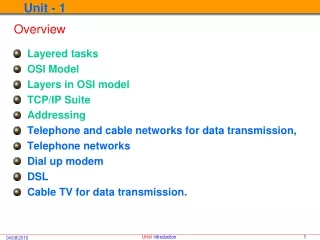
OBJECTIVES: • To discuss the idea of multiple layering in data communication and networking and the interrelationship between layers. • To discuss the OSI model and its layer architecture and to show the interface between the layers. • To briefly discuss the functions of each layer in the OSI model. • To introduce the TCP/IP protocol suite and compare its layers with the ones in the OSI model. • To show the functionality of each layer in the TCP/IP protocol with some examples. • To discuss the addressing mechanism used in some layers of the TCP/IP protocol suite for the delivery of a message from the source to the destination.
Chapter Outline 2.1 Protocol Layers 2.2 The OSI Model 2.3 TCP/IP Protocol Suite 2.4 Addressing
2-1 PROTOCOL LAYERS • A protocol is required when two entities need to communicate. • When communication is not simple, we may divide the complex task of communication into several layers. In this case, we may need several protocols, one for each layer.
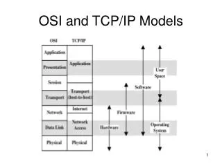
2-2 THE OSI MODEL • The International Standards Organization (ISO) is a multinational body dedicated to worldwide agreement on international standards. Established in 1947. • The Open Systems Interconnection (OSI) model An ISO standard that covers all aspects of network communications . It was first introduced in the late 1970s.
Note ISO is the organization; OSI is the model.
OSI Model… How to Memorize!
2-3 TCP/IP PROTOCOL SUITE • The TCP/IP protocol suite was developed prior to the OSI model. • Therefore, the layers in the TCP/IP protocol suite do not match exactly with those in the OSI model. • The original TCP/IP protocol suite was defined as four software layers built upon the hardware. • Today, however, TCP/IP is thought of as a five-layer model with the layers named similarly to the ones in the OSI model.
Note The unit of communication at the physical layer is a bit.
Note The unit of communication at the data link layer is a frame.
Note The unit of communication at the network layer is a packet.
Note The unit of communication at the transport layer is a segment, user datagram, or a segment, depending on the specific protocol used in this layer.
Note The unit of communication at the application layer is a message.
2-4 ADDRESSING • Four levels of addresses are used in an internet employing the TCP/IP protocols: • Physical address, • Logical address, • Port address, and • Application-specific address. • Each address is related to a one layer in the TCP/IP architecture
Example 2.3 In Figure 2.16 a node with physical address 10 sends a frame to a node with physical address 87. The two nodes are connected by a link (a LAN). At the data link layer, this frame contains physical (link) addresses in the header. These are the only addresses needed. The rest of the header contains other information needed at this level. As the figure shows, the computer with physical address 10 is the sender, and the computer with physical address 87 is the receiver. The data link layer at the sender receives data from an upper layer. It encapsulates the data in a frame. The frame is propagated through the LAN. Each station with a physical address other than 87 drops the frame because the destination address in the frame does not match its own physical address. The intended destination computer, however, finds a match between the destination address in the frame and its own physical address.
Example 2.4 Most local area networks use a 48-bit (6-byte) physical address written as 12 hexadecimal digits; every byte (2 hexadecimal digits) is separated by a colon, as shown below: 07:01:02:01:2C:4B A 6-byte (12 hexadecimal digits) physical address
Example 2.5 Figure 2.17 shows a part of an internet with two routers connecting three LANs. Each device (computer or router) has a pair of addresses (logical and physical) for each connection. In this case, each computer is connected to only one link and therefore has only one pair of addresses. Each router, however, is connected to three networks. So each router has three pairs of addresses, one for each connection. Although it may be obvious that each router must have a separate physical address for each connection, it may not be obvious why it needs a logical address for each connection. The computer with logical address A and physical address 10 needs to send a packet to the computer with logical address P and physical address 95. We use letters to show the logical addresses and numbers for physical addresses, but note that both are actually numbers.
Note The physical addresses will change from hop to hop, but the logical addresses remain the same.
Example 2.6 Figure 2.18 shows two computers communicating via the Internet. The sending computer is running three processes at this time with port addresses a, b, and c. The receiving computer is running two processes at this time with port addresses j and k. Process a in the sending computer needs to communicate with process j in the receiving computer. Note that although both computers are using the same application, FTP, for example, the port addresses are different because one is a client program and the other is a server program.
Note The physical addresses change from hop to hop, but the logical and port addresses usually remain the same.
Example 2.7 A port address is a 16-bit address represented by one decimal number as shown. 753 A 16-bit port address represented as one single number
Application-Specific Addresses • E-mail Address • E.g. gohar.m@superior.edu.pk • Uniform Resource Locator (URL) • E.g. www.superior.edu.pk