Download
1 / 9
90 likes | 157 Views
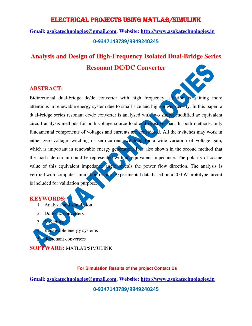
Bidirectional dual-bridge dc/dc converter with high frequency isolation is gaining more attentions in renewable energy system due to small size and high-power density. In this paper, a dual-bridge series resonant dc/dc converter is analyzed with two simple modified ac equivalent circuit analysis methods for both voltage source load and resistive load. In both methods, only fundamental components of voltages and currents are considered. All the switches may work in either zero-voltage-switching or zero-current-switching for a wide variation of voltage gain, which is important in renewable energy generation. It is also shown in the second method that the load side circuit could be represented with an equivalent impedance. The polarity of cosine value of this equivalent impedance angle reveals the power flow direction. The analysis is verified with computer simulation results. Experimental data based on a 200 W prototype circuit is included for validation purpose.

E N D
ELECTRICAL PROJECTS USING MATLAB/SIMULINK ELECTRICAL PROJECTS USING MATLAB/SIMULINK Gmail:asokatechnologies@gmail.com, Website: http://www.asokatechnologies.in 0-9347143789/9949240245 Analysis and Design of High-Frequency Isolated Dual-Bridge Series Resonant DC/DC Converter ABSTRACT: Bidirectional dual-bridge dc/dc converter with high frequency isolation is gaining more attentions in renewable energy system due to small size and high-power density. In this paper, a dual-bridge series resonant dc/dc converter is analyzed with two simple modified ac equivalent circuit analysis methods for both voltage source load and resistive load. In both methods, only fundamental components of voltages and currents are considered. All the switches may work in either zero-voltage-switching or zero-current-switching for a wide variation of voltage gain, which is important in renewable energy generation. It is also shown in the second method that the load side circuit could be represented with an equivalent impedance. The polarity of cosine value of this equivalent impedance angle reveals the power flow direction. The analysis is verified with computer simulation results. Experimental data based on a 200 W prototype circuit is included for validation purpose. KEYWORDS: 1.Analysis and simulation 2.Dc-to-dc converters 3.Modeling 4.Renewable energy systems 5. Resonant converters SOFTWARE: MATLAB/SIMULINK For Simulation Results of the project Contact Us Gmail:asokatechnologies@gmail.com, Website: http://www.asokatechnologies.in 0-9347143789/9949240245
ELECTRICAL PROJECTS USING MATLAB/SIMULINK ELECTRICAL PROJECTS USING MATLAB/SIMULINK Gmail:asokatechnologies@gmail.com, Website: http://www.asokatechnologies.in 0-9347143789/9949240245 BLOCK DIAGRAM: Fig. 1. Hybrid renewable energy generation system with battery back-up function. For Simulation Results of the project Contact Us Gmail:asokatechnologies@gmail.com, Website: http://www.asokatechnologies.in 0-9347143789/9949240245
ELECTRICAL PROJECTS USING MATLAB/SIMULINK ELECTRICAL PROJECTS USING MATLAB/SIMULINK Gmail:asokatechnologies@gmail.com, Website: http://www.asokatechnologies.in 0-9347143789/9949240245 EXPECTED SIMULATION RESULTS: Fig. 2. Output power versus phase-shift angle φ. (a) F = 1.1, M = 0.95, and different Q. (b) F = 1.1, Q = 1, and different converter gain M. For Simulation Results of the project Contact Us Gmail:asokatechnologies@gmail.com, Website: http://www.asokatechnologies.in 0-9347143789/9949240245
ELECTRICAL PROJECTS USING MATLAB/SIMULINK ELECTRICAL PROJECTS USING MATLAB/SIMULINK Gmail:asokatechnologies@gmail.com, Website: http://www.asokatechnologies.in 0-9347143789/9949240245 Fig. 3. Operation in charging mode (Vi= 110 V, Vo= 100 V), simulated waveforms of vAB and vCD , resonant current iS, resonant capacitor voltage vCs, output current before filter capacitor iofor output power (a) Po= 200W, (b) Po= 100 W, and (c) Po= 20 W. For Simulation Results of the project Contact Us Gmail:asokatechnologies@gmail.com, Website: http://www.asokatechnologies.in 0-9347143789/9949240245
ELECTRICAL PROJECTS USING MATLAB/SIMULINK ELECTRICAL PROJECTS USING MATLAB/SIMULINK Gmail:asokatechnologies@gmail.com, Website: http://www.asokatechnologies.in 0-9347143789/9949240245 Fig. 4. Operation in regeneration mode (Vi = 110V, Vo = 100 V). Simulated waveforms of vAB and vCD , resonant current iS , resonant capacitor voltage vCs , output current before filter capacitor io for output power Po= −200 W. Fig. 5. Full-load test results (Vi= 110 V, Vo= 100 V). (a) From top to bottom vAB (100V/div), vCD (100V/div), is (2A/div). (b) vC(100V/div). (c) Primary switch current (1A/div). (d) Secondary switch current (1A/div). For Simulation Results of the project Contact Us Gmail:asokatechnologies@gmail.com, Website: http://www.asokatechnologies.in 0-9347143789/9949240245
ELECTRICAL PROJECTS USING MATLAB/SIMULINK ELECTRICAL PROJECTS USING MATLAB/SIMULINK Gmail:asokatechnologies@gmail.com, Website: http://www.asokatechnologies.in 0-9347143789/9949240245 Fig. 6. (a) Half-load test results (Vi = 110 V, Vo = 100 V): from top to bottom: vAB (100 V/div), vCD (100 V/div), is (2 A/div), primary switch current (1 A/div), secondary switch current (1 A/div). (b) 10% load condition test results (Vi = 110 V, Vo = 100 V): from top to bottom: waveforms of (a) repeated. For Simulation Results of the project Contact Us Gmail:asokatechnologies@gmail.com, Website: http://www.asokatechnologies.in 0-9347143789/9949240245
ELECTRICAL PROJECTS USING MATLAB/SIMULINK ELECTRICAL PROJECTS USING MATLAB/SIMULINK Gmail:asokatechnologies@gmail.com, Website: http://www.asokatechnologies.in 0-9347143789/9949240245 Fig. 7. Output current of secondary converter under different load levels (Vi = 110 V, Vo = 100 V). (a) 200 W (2A/div). (b) 100 W (2A/div). (c) 20 W (1A/div). For Simulation Results of the project Contact Us Gmail:asokatechnologies@gmail.com, Website: http://www.asokatechnologies.in 0-9347143789/9949240245
ELECTRICAL PROJECTS USING MATLAB/SIMULINK ELECTRICAL PROJECTS USING MATLAB/SIMULINK Gmail:asokatechnologies@gmail.com, Website: http://www.asokatechnologies.in 0-9347143789/9949240245 CONCLUSION: In this paper, a HF isolated dual-bridge series resonant dc/dc converter has been proposed, which is suitable for renewable energy generation applications. Two modified ac equivalent circuit analysis methods were presented to analyze the DBSRC. First method used was voltage-source type of load, whereas, second method uses a controlled rectifier with resistive load. It was shown that an equivalent impedance could be used to represent the secondary part circuit in the case of resistive load to include the bidirectional feature. Detailed analysis has been presented for both the methods. Same results were obtained from both the methods. ZVS turn-ON for primary-side switches and ZCS turn-OFF for secondary-side switches could be achieved for all load and input/output voltage conditions. Design procedure has been illustrated by a 200Wdesign example. Through the SPICE simulation and experimental results, the theoretical results have been verified. In the DAB converter, performance of the converter is heavily dependent on the leakage inductance of the transformer (used for power transfer and should be as small as possible) [15], [19], whereas, in the DBSRC, leakage inductance is used as part of resonant tank. If the DAB converter is used for application with wide input/output voltage variation, ZVS of primary-side converter may be hard to achieve [19]. DBSRC has low possibility of transformer saturation due to the series capacitor (that can be split as mentioned earlier). The disadvantage of DBSRC is the size of resonant tank (additional capacitor), which brings extra size and cost. Further work is required to compare the DAB converter with the DBSRC for such applications. In the future, more study will be done based on the DBSRC. Efforts will focus on modifications to realize ZVS on the secondary side to reduce the switching losses further. With all two quadrant switches replaced with four-quadrant switches [23], the converter could be controlled as an ac/ac electronic transformer, which can be used in doubly fed induction generator (DFIG) based wind For Simulation Results of the project Contact Us Gmail:asokatechnologies@gmail.com, Website: http://www.asokatechnologies.in 0-9347143789/9949240245
ELECTRICAL PROJECTS USING MATLAB/SIMULINK ELECTRICAL PROJECTS USING MATLAB/SIMULINK Gmail:asokatechnologies@gmail.com, Website: http://www.asokatechnologies.in 0-9347143789/9949240245 generation system. For high-power applications, multicells of the converter may be used to meet high power density requirements. REFERENCES: [1] L. H. Hansen, L. Helle, F. Blaabjerg, E. Ritchie, S. Munk-Nielsen, H. Bindner, P. Sørensen, and B. Bak-Jenseen, “Conceptual survey of generators and power electronics for wind turbines,” Risø Nat. Lab., Roskilde, Denmark, Tech. Rep. Risø-R-1205(EN), ISBN 87-550-2743-8, Dec. 2001. [2] N. Kasa, Y. Harada, T. Ida, and A. K. S. Bhat, “Zero-current transitions converters for independent small scale power network system using lower power wind turbines,” in Proc. IEEE Int. Symp. Power Electron., Electric Drives, Autom. Motion 2006, May 23–26, pp. 1206–1210. [3] J. Lai and D. J. Nelson, “Energy management power converters in hybrid electric and fuel cell vehicles,” Proc. IEEE, vol. 95, no. 4, pp. 766–777, Apr. 2007. [4] H. Tao, A. Kotsopoulos, J. L. Duarte, andM. A.M. Hendrix, “Multi-input bidirectional dc-dc converter combining dc-link and magnetic-coupling for fuel cell systems,” in Proc. 40th IEEE IAS Annu. Meet., Oct. 2005, vol. 3, pp. 2021–2028. [5] F. Z. Peng, H. Li, G.-J. Su, and J. S. Lawler, “A new ZVS bidirectional dc–dc converter for fuel cell and battery application,” IEEE Trans. Power Electron., vol. 19, no. 1, pp. 54–65, Jan. 2004. For Simulation Results of the project Contact Us Gmail:asokatechnologies@gmail.com, Website: http://www.asokatechnologies.in 0-9347143789/9949240245