Download
1 / 7
70 likes | 145 Views
Solar Grid-Tied Inverter system is an electricity generating system that is connected to the utility grid. This paper discusses the design of a Grid-Tied Inverter (GTI). The first stage is Maximum Power Point Tracking (MPPT) which is implemented using perturb and observe algorithm. Then push pull converter is used to convert DC output from MPPT stage to 330V dc. This DC voltage is then converted into AC voltage using full-wave inverter topology employing unipolar SPWM technique. Then synchronization is achieved between grid and photovoltaic system. Finally, power flow control mechanism controls the power flow from GTI system to the grid and the house load.

E N D
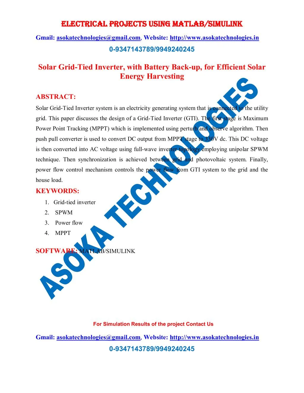
ELECTRICAL PROJECTS USING MATLAB/SIMULINK ELECTRICAL PROJECTS USING MATLAB/SIMULINK Gmail:asokatechnologies@gmail.com, Website: http://www.asokatechnologies.in 0-9347143789/9949240245 Solar Grid-Tied Inverter, with Battery Back-up, for Efficient Solar Energy Harvesting ABSTRACT: Solar Grid-Tied Inverter system is an electricity generating system that is connected to the utility grid. This paper discusses the design of a Grid-Tied Inverter (GTI). The first stage is Maximum Power Point Tracking (MPPT) which is implemented using perturb and observe algorithm. Then push pull converter is used to convert DC output from MPPT stage to 330V dc. This DC voltage is then converted into AC voltage using full-wave inverter topology employing unipolar SPWM technique. Then synchronization is achieved between grid and photovoltaic system. Finally, power flow control mechanism controls the power flow from GTI system to the grid and the house load. KEYWORDS: 1.Grid-tied inverter 2. SPWM 3. Power flow 4. MPPT SOFTWARE: MATLAB/SIMULINK For Simulation Results of the project Contact Us Gmail:asokatechnologies@gmail.com, Website: http://www.asokatechnologies.in 0-9347143789/9949240245
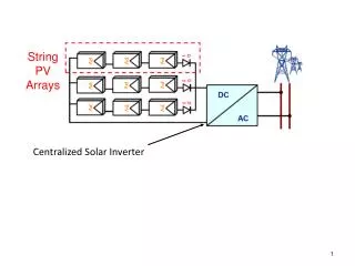
ELECTRICAL PROJECTS USING MATLAB/SIMULINK ELECTRICAL PROJECTS USING MATLAB/SIMULINK Gmail:asokatechnologies@gmail.com, Website: http://www.asokatechnologies.in 0-9347143789/9949240245 CIRCUIT DIAGRAM: Figure 1. Cuk converter. Figure 2. Full wave inverter topology . For Simulation Results of the project Contact Us Gmail:asokatechnologies@gmail.com, Website: http://www.asokatechnologies.in 0-9347143789/9949240245
ELECTRICAL PROJECTS USING MATLAB/SIMULINK ELECTRICAL PROJECTS USING MATLAB/SIMULINK Gmail:asokatechnologies@gmail.com, Website: http://www.asokatechnologies.in 0-9347143789/9949240245 EXPECTED SIMULATION RESULTS: Figure 3. Inverter output before filter Figure 4. Inverter output after filter. For Simulation Results of the project Contact Us Gmail:asokatechnologies@gmail.com, Website: http://www.asokatechnologies.in 0-9347143789/9949240245
ELECTRICAL PROJECTS USING MATLAB/SIMULINK ELECTRICAL PROJECTS USING MATLAB/SIMULINK Gmail:asokatechnologies@gmail.com, Website: http://www.asokatechnologies.in 0-9347143789/9949240245 Figure 5. Simulink circuit to demonstrate power flow. Figure 6. GTI output power. For Simulation Results of the project Contact Us Gmail:asokatechnologies@gmail.com, Website: http://www.asokatechnologies.in 0-9347143789/9949240245
ELECTRICAL PROJECTS USING MATLAB/SIMULINK ELECTRICAL PROJECTS USING MATLAB/SIMULINK Gmail:asokatechnologies@gmail.com, Website: http://www.asokatechnologies.in 0-9347143789/9949240245 Figure 7. Grid output power. Figure 8. Power through inductor. For Simulation Results of the project Contact Us Gmail:asokatechnologies@gmail.com, Website: http://www.asokatechnologies.in 0-9347143789/9949240245
ELECTRICAL PROJECTS USING MATLAB/SIMULINK ELECTRICAL PROJECTS USING MATLAB/SIMULINK Gmail:asokatechnologies@gmail.com, Website: http://www.asokatechnologies.in 0-9347143789/9949240245 Figure 9. GTI output power. Figure 10. Grid output power. For Simulation Results of the project Contact Us Gmail:asokatechnologies@gmail.com, Website: http://www.asokatechnologies.in 0-9347143789/9949240245
ELECTRICAL PROJECTS USING MATLAB/SIMULINK ELECTRICAL PROJECTS USING MATLAB/SIMULINK Gmail:asokatechnologies@gmail.com, Website: http://www.asokatechnologies.in 0-9347143789/9949240245 Figure 11. Power through inductor. REFERENCES: [1] Power Electronics: Circuits, Devices and Applications, 3/E by M. H. Rashid, Prentice Hall, 2004J. Clerk Maxwell, A Treatise on Electricity and Magnetism, 3rd ed., vol. 2. Oxford: Clarendon, 1892, pp.68–73. [2] Electric Machinery Fundamentals by Stephen J. Chapman, 4th Edition, McGraw-Hill, 2005K. Elissa, “Title of paper if known,” unpublished. [3] M. A. Salam, Fundamentals of Power Systems, Alpha Science Oxford, UK International Ltd., 2009. [4] T. Kwang and S. Masri, “Grid Tie Photovoltaic Inverter forResidential Application,” Modern Applied Science, vol. 5, No. 4, Aug. 2011, pp. 3-4, doi:10.5539/mas.v5n4p200 For Simulation Results of the project Contact Us Gmail:asokatechnologies@gmail.com, Website: http://www.asokatechnologies.in 0-9347143789/9949240245