Download
1 / 23
290 likes | 1.05k Views
Modern Combined Cycle Power Plants – Improvement of a high efficient and clean technology O. Kreyenberg, H. Schütz, H. Friede Siemens PG. "Energy Efficiency in IPPC-installations" 21 and 22 October 2004 Vienna. Agenda. Market Drivers. Reference Power Plant Product Overview

E N D
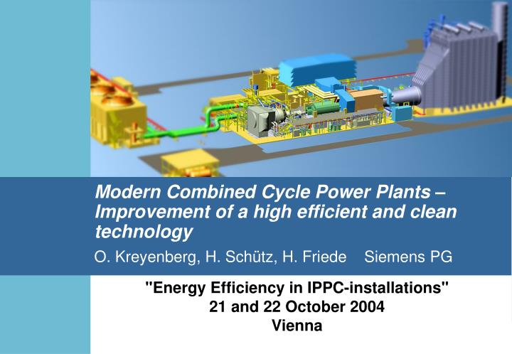
Modern Combined Cycle Power Plants – Improvement of a high efficient and clean technologyO. Kreyenberg, H. Schütz, H. Friede Siemens PG "Energy Efficiency in IPPC-installations" 21 and 22 October 2004 Vienna
Agenda Market Drivers Reference Power Plant Product Overview - Steam Power Plant - Combined Cycle Power Plant Reference Power Plant Design Philosophy Design Targets References
Efficiency Risk Guarantee* Overall Construction Time Price The Market Conditions Have Changed Dramatically in the Power IndustryOver the Last 10 Years Market Conditions Years * technical warranties (NOx, et. al.), delivery time
Life Cycle Cost (LCC) Analysis Parameters influenced by the supplier Parameters Costs Investment costs Financing costs Service life Demolition costs Reduction of specificinvestment costs Global sourcing Modular design Short delivery times Capital costs Live Cycle Costs Fuel contractconditions Efficiency Fuel Costs High process and component efficiencies Personnel costs Consumables/waste Spare parts Maintenance Optimized level ofautomation High availability Ease of maintenance Operating costs
Varioplant 300 300- 450 MW 700 500- 750 MW 900 800- 1000 MW Gas/Oil Single-Shaft 50 Hz 100, 290, 400 MW Multi-Shaft 50 Hz 200, 580, 800 MW60 Hz 200, 540, 730 MW 60 Hz 100, 270, 365 MW Our Reference Power Plants are Focused on International Main Market Demand for IPP’s Coal/Oil Customized... of the shelf... Components, Islands and Turnkey Gas/Oil
Multi-Shaft Combined Cycle Power Plant Econopac Arrangement • ECONOPAC • Gas turbine • Gas turbine generator • Air intake • Exhaust gas system • Fuel system • Electrical package (SFC/SEE) • GT - Auxiliaries • Fire protection • Options
Multi-Shaft Combined Cycle Power Plant Power Island Arrangement • POWER ISLAND • Econopac • Steam turbine • Steam turbinegenerator incl. SEE • Heat recoverysteam generator • Major pumps • Condenser • Critical valves • ST - Auxiliaries • Cycle optimization • Fuel gas pre-heater • Options
Multi-Shaft Combined Cycle Power Plant Turnkey (Cooling Tower) • TURNKEY • Power Island • Fuel supply systems • Cooling systems • Water treatment • Raw water system • Waste water system • Tanks • Cranes/hoists • Buildings/structures • Fire protection • Plant piping/valves • Plant electrical • Further options
Multi-Shaft Combined Cycle Power Plant Turnkey with House (Cooling Tower) • TURNKEY • Power Island • Fuel supply systems • Cooling systems • Water treatment • Raw water system • Waste water system • Tanks • Cranes/hoists • Buildings/structures • Fire protection • Plant piping/valves • Plant electrical • Further options
Evolution of Combined Cycle Power Plant Efficiency Steam cycle Single pressure Dual pressure Tripple pressure with reheat Net efficiency(%) 60 Turbine inlettemp. (ISO) Fuel preheating Life steampressure Life steamtemperature 1160°C — 100 bar 520°C 1250°C 200°C 160 bar 580°C 58 1230°C 130°C 125 bar 565°C 1230°C 130°C 110 bar 550°C 1120°C — 80 bar 520°C 1190°C 200°C 110 bar 540°C 56 1050°C — 75 bar 510°C 54 1000°C — 60 bar 485°C 52 960°C — 50 bar 460°C Fuel gas firing ISO ambient conditions (15°C, 1013 mbar, 60% rel. humidity) Condenser back pressure 0.04 bar 50 48 46 1983/84 1987/88 1990/91 1992/93 1994/95 1996/97 1998/99 2001 2005/06 Year of commissioning Source: Siemens Gas Turbines
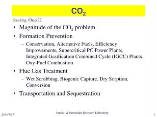
. mKL Power Output, Efficiency, NOx-Emission and Cooling Air Demand versus Combustion Temperature Boundary conditions: The same technology for blade cooling, combustion chamber cooling and burner. Ex- haust gas 102% Gas turbine NOX Tcomb. Fuel 2% Heat recovery steam generator Combustion chamber Combustion air 80% NOX Air intake 100% Electricity Generator Cooling air 20% TCool.-air hGUD Steam turbine Circulating water Electricity TIT Generator Condenser 1570°C 1700°C TCombustion
Efficiency Improvements due to Increasing the Number of Pressure Stages Temperature curves in aheat recovery steam generator Efficiency increase D h net [%-points] Temperature [°C] 1-pressure process 2-pressure process 3-pressure process 125 bar/565 °C28 bar/565 °C4 bar/235 °C 3 600 125 bar/565 °C29 bar/320 °C5 bar/200 °C 500 Exhaust gas 400 2 80 bar/540 °C5 bar/210 °C 300 2.8 2.1 1 200 1.6 100 65 bar/540 °C 54.1% 0 0 Transfered heat 1-pressure 2-pressure 3-pressurewithoutreheat 3-pressure withreheat
Quick Start up Increases Plant Utilisation Factor... GT at full load/Bypass System closed Start-up after 8h Shut-down Plant start-up with improved equipment Typical plant start-up Plant Load [MW] ≈ 40 min ≈ 90 min Time
Relationship between turbine inlet temperature and NOx emissions A temperature increase by 70K doubles the NOx- emissions !
One the way to the Technical leadership nowtomorrow Efficiency 58%* > 59% TIT** 1230°C 1290°C NOx 25 ppm 9 – 15 ppm * depending on cooling conditions ** turbine inlet temperature Details on additional measures will be presented at a VDI Symposium in Leverkusen 23./24. November 2004
Mainz-Wiesbaden, Germany Combined Cycle Power Plant V94.3Awith Steam Extraction Mainz - Wiesbaden (Germany) Concept: Multi Shaft 1+1 V94.3A Output (nat. gas, site) : 1 x 400 MW Efficiency (nat. gas, site): >58,4 %* COD: July 2001 Fuels: Natural Gas (Fuel oil Back up) Contract: EPC TK plus 10 y. S&M
Pulau Seraya, Singapore: 2 CC 1S.V94.3AThe Most Efficient Plant in SEA Pulau Seraya (Singapore) Concept: Single Shaft 1S.V94.3A Output (nat. gas, site) : 2x 367 MW Efficiency (nat. gas, site): >57.2 % COD: November 2002 Fuels: Natural Gas (Fuel oil Back up) Contract: EPC TK plus 10 y. S&M