Download
1 / 12
120 likes | 124 Views
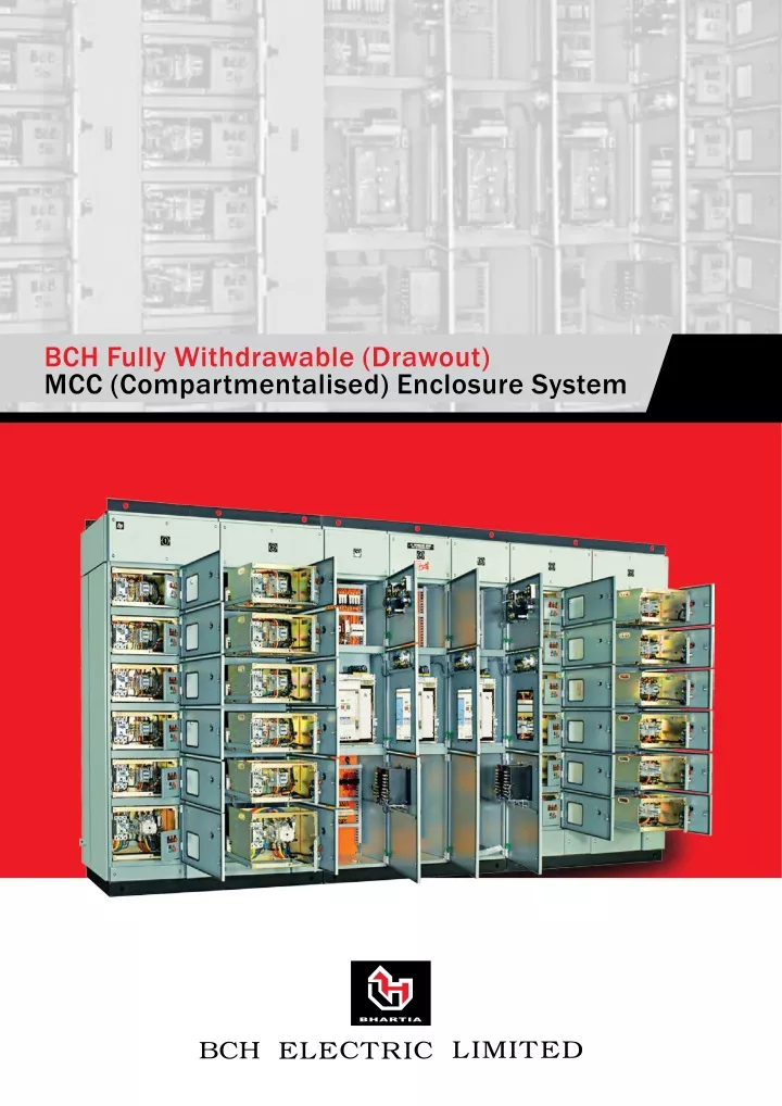
BCH Motor Control Center and Power Control Center are fully compartmentalized modular construction, dust and vermin proof Modules, horizontal and vertical bus bar chambers and vertical cable chambers are provided with independent doors and covers with PU foam gaskets. for more info visit our website -https://bchindia.com/product/mcc-pcc/

E N D
Withdrawable or Fixed-Pattern? Compared to fixed-pattern assemblies, withdrawable / Drawout MCC provide: • Greater stacking densities • Easier upgrades when incorporating new equipment. • Compartments that can be interchanged safely and quickly, reducing breakdown time in process industries. • Clear, visible indication for disconnected compartments, giving increased safety for operators. Here’s what you should know about BCH Drawout MCC • BCH make Drawout Motor Control Centre is a free-standing and floor mounting type switchboard available both in single front and double front versions, suitable for indoor installation. • Each vertical panel is divided into distinct zones for power busbars, control busbars, feeders, power terminal and auxiliary contact wiring. • Horizontal busbars (HBB) are located at the top of the panels. The phase sequence is R-Y-B-N. Where the number of bars per phase exceeds one, the HBB is split into two / three packets per phase. The phase sequence is R1-Y1-B1-R2-Y2-B2-N for two packets. • The droppers are located behind the unit feeder compartment and isolated from the unit feeder compartment with an insulating barrier. The phase sequence, as seen from front left to right, is R-Y-B-N. • The incoming power contacts are located on the Left hand side, while the outgoing power contacts are located on the right hand side. • The starter unit in the fully drawout version has the following positions: • Service (connected) position. • Test position. • Isolated (disconnected) position. • The Service (connected) / Test / Isolated (disconnected) positions are indicated by STI locator pin, mounted on the trolley and the identification sticker pasted on the bottom separation plate. • Self disconnecting, pull-apart, plug and socket type 10 way control contacts, i.e. the Secondary Isolating Contacts (SICs) are mounted in back of the trolley unit. • To facilitate transportation, the MCC is split into multiple sections. Each section is wrapped in an HDPE cover and packed in a wooden case. GENERAL ARRANGEMENT AND DIFFERENT DESIGN FEATURES Standard module dimension is : Single Front: 900(w) x 2400 (h) x 600 (d) mm Double Front: 900(w) x 2400 (h) x 1200 (d) mm 2 | www.bchindia.com
* For both sizes height 2400mm includes 100mm high base frame / plinth. * The component mounting compartment has a width of 600mm and the outgoing cable alley width is 300mm, thus making the single vertical panel width of 900mm. Both the above designs incorporate the same design of withdrawable modules, busbar system and principle of 100% modular construction. Removable lifting angles are provided on the top. IP-54 ingress protection is retained with angles removed. The foundation channels and lifting angles run full length of the transportable unit. Maximum width of the transportable unit is limited to 1800mm. Sheet thickness is 2mm for all load bearing members. All Doors and Covers are provided with special aluminum extruded hinge and compressive jointless PU Foam gasket. Metal Treatment : Rigorous metal treatment and surface coating is provided to the sheet metal components used in construction of MCC. This makes the MCC suitable for operation in high ambient temperature, humidity and tropical atmospheric conditions. A fully automatic ten tank spraying process is used for metal treatment. This treatment followed by electrostatic coating of epoxy based powder paint which is cured in a continuous converyorised oven. The powder coated film thus ensures a non-porous surface and provide superior resistance against scratching corrosion and weathering. BCH standard paint shade for MCC is RAL-7035 structure finish. Drawout Trolley components are zinc electroplated. The automated powder coating process flow chart: Material from shop Loading of components Knockoff Degreasing Activation Water Rinsing 1 and 2 Degreasing Zinc Phosphating Water Rinsing 3 and 4 DM Water Rinsing Powder Coating Material Dry off Oven Fresh DM Water Rinsing Powder Baking Oven Unloading and up keeping www.bchindia.com | 3
Busbar System: Superiority of material, design and construction combine to provide an exceptionally strong and fault-immune- busbar system in the MCC. Busbars are fabricated from aluminum (E91E as per IS 5082) or electrolytic grade copper conforming to IS 1897, as per customer preference. Busbar supports are moulded from thermosetting fiberglass reinforced polyester material having high impact and tensile strength, high tracking index, properties of high temperature withstand and fire retardant, high insulation breakdown voltage. For each phase (standard cross-section: 40x10mm aluminum) double vertical busbar are provided. Horizontal busbar strength is ensured by edgewise mounting of busbars in finger supports. Cabling Space: Both types (single / double front) of MCC enclosures are designed for greater cabling convenience. Bottom entry is available as standard in both models with liberal openings for cables. Top entry can also be provided, as an option. Horizontal busbars are always located at the top irrespective of cable entry direction. Terminals for external power / control connections are accessible with module trolley in position. The wide cable alley makes bending and termination of cables easy. 4 | www.bchindia.com
Module Space: The height available for compartments in each vertical is 1800mm or 18 space units (SU) of 100mm each. Compartment height is extensible in multiples of 100mm. Minimum compartment height starts from 200mm (2SU) to maximum up to 800mm (8SU). Drawout Units: Each drawout module is an independent unit with incoming and outgoing power stab-on contacts and self disconnecting control sliding contacts. The drawout unit is mounted on precision telescopic slides to ensuring alignment and ease movement. Fully drawout module has three distinct functional positions: Service: Power & Control contacts engaged. Test: Control circuits can be tested. Power contacts disconnected. Isolated: Both Power and Control contacts disengaged. Service Test Isolated Out for Maintenance www.bchindia.com | 5
Contacts: All power and control contacts are silver plated. They offer high resistance to abrasion, lower mV drop, leading to lower wear and tear and longer life of the contacts. The power contacts are adequately insulated. Module incoming power contacts have a rating of 100, 150 & 300 Amps and engage directly with riser bars which are of tinplated copper. Control contacts are self disconnecting, pull-apart, plug and socket type with thermal rating of 25 Amps. The contacts are finger touch proof. In isolated position of module, the fixed socket portion of control contacts can safely remain live. All outgoing contact mountings are floating type with unique self aligning and positive mating features. Contacts housings are made of fiberglass reinforced thermosetting material for adequate thermal and mechanical strength. Power Outgoing Contact Control Contact Power In-coming Contact Short-Circuit Strength: Busbar tested for short circuit withstand capacity 50KA for 1 sec. – not only for the phases but for neutral too. Design ensures that busbar insulation remains healthy after sustaining each fault of this magnitude occurring at peak load operating condition. SAFETY AND MAINTENANCE FEATURES Busbars and droppers are provided with heat shrunk PVC sleeving. The heat curing process ensures no voids or pinholes. Except at the tap-offs and stab-in contact plates, the busbars are completely covered with insulating material. Sleeving also protects busbars against accidental contacts with hardware, tools and vermin. Joint shrouds are provided to cover tap-offs and fish-plate joints. Thus short circuits between phase and neutral or earth is virtually eliminated in the bus zone. The heat shrunk PVC sleeving is provided in addition to the large clearances in the busbar zone. Busbar Supports: The busbar supports are moulded from fiber glass reinforced thermosetting plastic. This material has higher mechanical strength compared to conventional support material. Ribbed construction of moulded supports prevents tracking caused by dust accumulation. FRP support for Busbar Dropper Finger Support For Hor. Busbar 6 | www.bchindia.com
Fixed Safety Barrier: Fixed type high quality FR4 FRP grade barrier between vertical bus bar and trolley feeder will provide 100% protection against direct contact with live bus bars. Earthing of Trolleys: Earthing of withdrawable modules in Service an and Test positions is ensured by a spring loaded scraping earth contact on the module barrier. Silver plated scraping earth contact on each drawout module is ‘Make-first’ and ‘Break-last’ type. This arrangement ensures that not only adequately rated earthing system is available under load conditions but also earth continuity is maintained when the module is under test (control circuit energized) All doors are individually earthed. Mechanical Interlock System & STI Locator: The circuit breakers are provided with mechanical door interlocks to prevent opening of door when the unit is in energized condition. The Service (connected) / Test / Isolate (disconnected) positions are indicated by STI locator pin, mounted bottom plate of the compartment and the identification sticker pasted on the withdrawable unit. www.bchindia.com | 7
Telescopic Rails & Racking Screw Offer: • Positive guidance • Smooth movement of the module • Perfect alignment of contacts • They eliminate the need to remove the module for routine checks / minor modifications. All identical drawout units are fully interchangeable thus minimising downtime. Command Module or Control Plate: Indicating lamps, push buttons, meters and selector switches are mounted on a control plate. This plate can be hinged out for inspection / maintenance of the connections. Only the control plate needs to be changed in case of change in specified control equipment. 8 | www.bchindia.com
TECHNICAL DATA Insulation 660 volts, 40-60 Hz. Power Circuit Upto 550 volts AC, 3 ph. 50 HZ with or without Neutral. Control Circuit 110 Volts, 230 Volts, or any Voltage upto 440 Volts AC or 220 Volts DC. Aluminium grade E 91E as per IS:5082 & Electrolytic grade Copper Busbars for current rating up to 6300amps. Rated Current Busbar system designed for 50 KA rms / 1sec, and Strength 105 KA peak fault withstand as per IS: 8623 and IEC: 61439 (Tested from CPRI – Bhopal) Short Circuit Temperature Rise Panel tested for 800A to 4000A from CPRI Bhopal as per IS: 8623 and IEC: 61439. Ambient Temperature Standard 450 degrees Centigrade. Degree of Protection IP 54 as per IS 13947-1 and IEC : 60529 upto 1600A and IP 43 beyond 1600A. Busbar System TP-E or TPN-E. Panel Height 2400mm, (including 100mm High plinth) Panel width 900mm Panel depth 600mm, 1200mm www.bchindia.com | 9
HIGHLIGHTS & SALIENT FEATURES oF BCH TECHNo-MoDULE DRAwoUT MCC • Each drawout module has interchangeability with same size of feeder. • Extra strong horizontal busbar system using robust FRP supports. • CPRI tested for short circuit upto 50 KA rms/1 sec. • High withstands against effects of internal arcing faults without endangering operating personnel. • Front Cabling version, with 300mm wide cable alley. • 100% bolted fabricated enclosure with internal hinges at all doors, removable lifting angles. • Modular construction allowing easy extensibility and site modification. Compact and varied sizes of modules. • Precision telescopic slides ensuring high degree of alignment. • Safety features like fixed FRP barrier, scraping earth, and fully compartmentalized design. • The similar drawout units are fully interchangeable. • All power and control contact housings designed with adequate shrouding and interpole barriers to ensure high creepage values. • 22.5 mm dia push buttons and lights enhance the aesthetic look. • Metal treatment with fully automatic ten tank process followed by electrostatic coating of epoxy based powder paint. • Self connecting & disconnecting power and auxiliary contacts. • Drawout modules are withdrawable with three distinct positions – Service, Test, Isolate. • Absolutely flexible – progressive & last minute design changes can be accommodated easily with little or no cost impact. • Reliable earthing of withdrawable units consistent with feeder rating. • Flexibility to partition the panel using separation plates internal segregation up to Form 4B • Self-disconnecting, pull-apart, plug and socket type 10 way control contacts, i.e. the Secondary Isolating Contacts (SICs) are mounted in back of the trolley unit. 10 | www.bchindia.com
BCH Electric Limited, an ISO 14001:2015 and ISO 9001:2015 company, is today one of the leading manufacturer of wide range of Industrial Enclosures. It is wholly owned Indian company with a wide network of global connections. BCH Electric, as always, remains committed to customer satisfaction & loyalty, and will continue to broaden its portfolio with more services and products to further strengthen its partnership with customers. Our diversified enclosure product portfolio consists of IP-55, IP-66 welded boxes both in mild steel as well as stainless steel, techno-modular enclosures, compartmentalized enclosures up-to form-4B, 19 inch rack, telecom enclosures, control desks, and in addition we can provide a customized enclosure solution for almost every need to protect your system. Our enclosures and panel solutions are brought to market by a sales and service network spanning across the entire nation with over 50 branch offices and resident engineer locations as well as over 500 active channel partners.