Download
1 / 6
60 likes | 68 Views
Limit switches is a electro-mechanical switch, which limits or stops the travel of an object, when it reaches the predetermined point. It is mechanically actuated or operated by the motion of the object itself. The mechanical actuator is further linked to set of normally open(NO) normally closed(NC) contacts. These set of contacts, make or break the supply to an electrical circuit. for more info visit our website - https://bchindia.com/product/limit-switches/

E N D
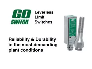
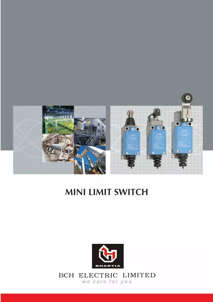
Mini Limit Switches Mini Limit Switches BCH Mini Limit Switches are designed with a single aim to improve productivity better....faster....with less production down time. These Limit Switches deliver flawless, continuous and consistent performance even in highly contaminated atmospheres and in high shock and vibration applications. Manufactured to worldclass and exacting standards, each product passes through Stringent Quality Tests. Typical Applications Typical Applications Features Features Compact design requiring less mounting space. Machine tools Excellent contact reliability using crossbar contact method. Material handling Dual cutoff circuit with minimum chatter and bounce. Food & beverages Zinc Die cast base & high end polyamide cover. Textile machinery Terminals spread in a tiered array allow ample wiring space Conveyors Dust-proof, waterproof, oil resistant construction. Packaging machinery Long mechanical & electrical life Technical Data Technical Data Ref. standards Operating temp limits Rated operating voltage (Ue) Rated insulation voltage (Ui) Rated impulse withstand voltage (Uimp) Rated Frequency Rated thermal current (Ith) Resistive Load AC 15 Duty DC 13 Duty IS 13947-5-1 EN 60947-5-1 -20 to + 600 C 250V 250V Conditional S. C. Current Short Ckt Protection Device Contact Combination Mech. Life Frequency of Operation Electrical Life IP category Pollution Degree Termination Tightening Torque Shock resistance as per IEC 68-2-27 condition 100A 10A fuse 1 NO+ 1 NC 10 million oprns. 7200 oprns / hr. 0.3 million oprns. IP 64 3 1.5 sq. mm. cable 0.6 Nm 10g in free condition, 30 g in fully operated 2.5kV 50/60 Hz 5A 5A, 250V AC 0.4 A, 125V DC 3A, 125V AC 2A, 250V AC 0.1A, 125 V DC Vibration resistance as per IEC 68-2-6 Max. 55 Hz
Operating Data Table Operating Data Table MOVEMENT DIFF. OVER TRAVEL (O.T) TOTAL TRAVEL (T.T) OPERATING FORCE PRE TRAVEL (P.T) RETURN FORCE Max. gms (N) Min. gms (N) Max. mm (M.D), Max. mm Min. mm Min. mm Push Plunger Roller Plunger Cross Roller Plunger 4 5.5 900 (8.83) 150 (1.47) 0.7 1.5 100 950 Roller Arm 200 600 (5.88) 50 (0.49) 750 800 (7.84)~ 342 (3.35) 50 (0.49)~ 21 (0.21) Adjustable Roller Arm 200 100 750 950 800 (7.84)~ 203 (1.99) 50 (0.49)~ 12 (0.12) Adustable Rod 200 950 100 750 Cat's Whisker - 90 (0.80) - 20 30 50 - Flexible Rod 50 70 - 20 90 (0.88) General Purpose 1000 (9.81) 1.5 - 5.8 - 4.3 Travel & Operation Diagrams Travel & Operation Diagrams Rotary Movement (DLSMRL/DLSMRLA/DLSMJWA) Linear Movement (DLSMRP/DLSMRP/DLSMRPX/DLSMPP/DLSMAR) P.T. Actuator T.T. a M.D. h T.T. O.T. P.T. Resetting O.T. Point M.D. Resetting T.T O.T M.D => P.T h a => => Total Travel Over Travel Movement Differential Pre Travel 80% of T.T. 450 => => =>
Catalogue Reference Table Catalogue Reference Table TYPE DESCRIPTION CAT. REF. Push Plunger Standard DLSMPP Standard DLSMRP Roller Plunger Cross DLSMRPX Roller Lever Standard - 30 mm DLSMRL Roller Lever Adjustable 30 mm - 70 mm DLSMRLA Rod Arm Adjustable DLSMJWA Flexible Rod Nylon DLSMSR Cat's Whisker Steel Wire DLSMSW General Purpose Standard DLSMAR
Dimensions (mm) Dimensions (mm) Adjustable Roller Arm (DLSMRLA) Adjustable Rod Arm (DLSMJWA) Roller Arm (DLSMRL) PT 20 max 0 (44.9) 41.2 0.8 + 36.2 0.8 47.7 0.8 + 42.7 0.8 + 33.5 0.8 5.55 PT 20 max Ø18x7 Nylon roller (Roller can be rotated and locked in any position through 360 ) + 0 PT 20 max 36.3 0.8 + + 0 Adjustable 30-118 Adjustable length of arm (30-70) 28.5 0.8 + 10.2 o R30 M4 arm fixing Screw (with hexagonal holes) 18.5 18.5 18.5 M4 arm fastening screw with hexagonal holes 12.5 12.5 12.5 Arm fastening 38.1 plate 56 56 0.3 64 64 56 64 + 2 (46.4) Roller/Cross Roller Plunger (DLSMRP/DLSMRPX) Cat Whisker(DLSMSW) Flexible Rod (DLSMSR) PT 30 max 10.2 10.2 10.2 PT 50 max Ø12.5x3.8 stainless steel roller plunger Ø3 Ø1.2 Steel Wire Nylon Rod 14.8 51.5 41.5 PT 1.5 Max Ø5.8 38 100 1.5 100 1.5 + + 2-Ø42 +0.2/0. Mounting holes 2-M5 (P=0.8) tapped 7 In deapth mounting holes M3x6 Cover Screw 4 20.4 0.3 + 56 64 56 0.3 + 56 0.3 + 64 2-M5 (P=0.8) tapped mounting holes 2-M3x23 Cover Scres 14 7.5 0.2 + 21 0.2 + 28 15.1 25 General Purpose (DLSMAR) Mounting Dimensions Through Hole Mounting Surface Mounting (Depth of Screws holes> 15mm) (Thickness of Panel< 5mm) 37.7 PT 1.5 Max 4 Nos. Ø5.5 4 Nos. M4 TAP 16.8 21 0.3 + Ø12.5x3.8 Stainless steel roller 10 21 0.2 + 10 56 0.3 + 56 64 56 0.2 + Push Plunger (DLSMPP) Ø7 Stainless Steel Plunger 10.2 3 PT 1.5 Max 26.5 56±0.3 64
RP / 5,000 / Jan. '08 IND-CONTROL/MINILIMIT/3000/DEC'04