Download
1 / 49
0 likes | 6 Views
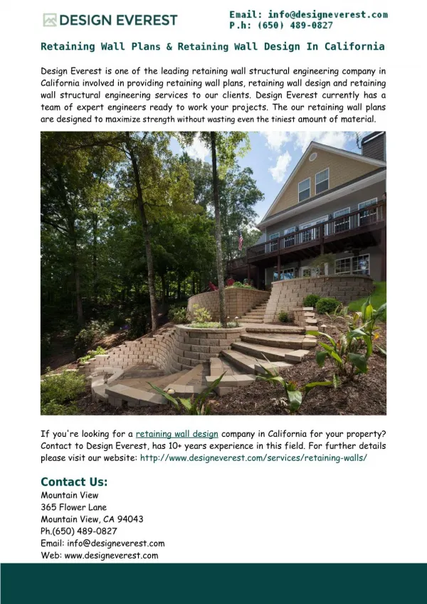
Design of Gravity and Cantilever Retaining Wall

E N D
Department of Civil Engineering Foundation Engineering-I (Ceng-3141) Chapter 4-1 DESIGN OF RETAINING WALLS
Lecture outline Introduction Common types of retaining walls • Gravity retaining walls • Semi-gravity retaining walls • Cantilever retaining walls • Buttress retaining walls • Counter-fort retaining walls Design of retaining walls • proportioning of retaining walls • check the stability • provide reinforcement, if required
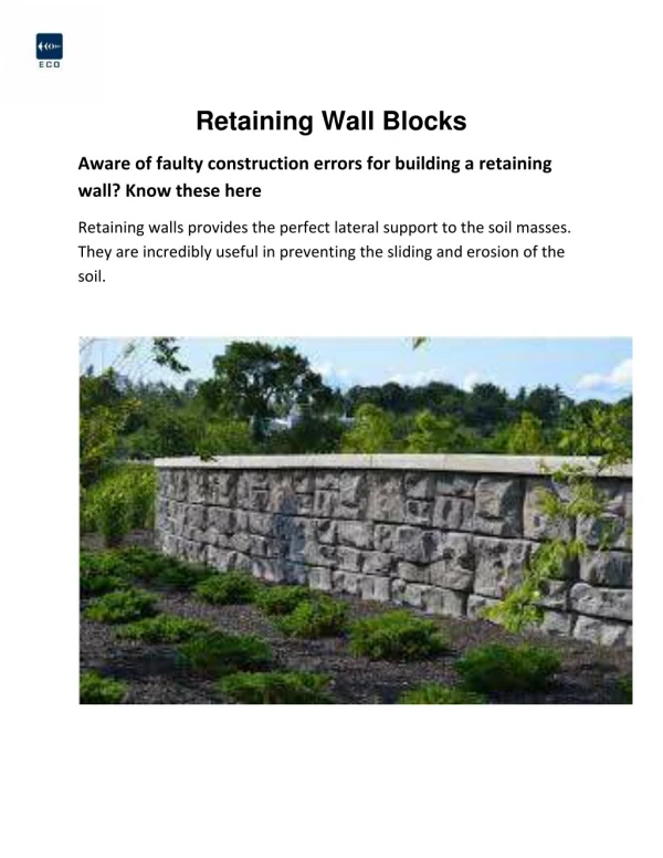
Introduction • Retaining walls are relatively rigid walls used for supporting the soil mass laterally or any. • Most retaining structures are vertical or nearly so. • The most common types of retaining walls are classified as under: • Gravity retaining walls • Semi-Gravity retaining walls • Cantilever retaining walls • Counter-fort retaining walls • Buttress retaining walls
1. Gravity Retaining Walls • Depend up on their weight for stability • Usually constructed of plain concrete or masonry. • Not economical for large heights • Trapezoidal in section with the base projecting beyond the face and back of the wall • In many cases, a small amount of steel may be used for the construction of gravity walls, thereby minimizing the size of wall section. • Such walls are called semi-gravity retaining walls
2. Cantilever Retaining Walls • Made of reinforced concrete that consists of a thin stem and a base slab. • Inverted T-shaped in section with each projecting acts as a cantilever • Economical to a height of about 8m stem heel toe
3. Counter-fort Retaining Walls • Have thin vertical slabs called counter-forts • Counter-forts spaced across the vertical stem at regular intervals. • The purpose of providing the counter-forts is to reduce the shear force and bending moments in the vertical stem and the base slab. • Economical for a height more than 6 to 8m.
same as counterfort except that the vertical brackets are on the opposite side of the backfill 4. Buttress walls Vertical stem Toe Heel
#Design of retaining walls There are two phases in the design of retaining walls:- • The structure as a whole is checked for stability- knowing the lateral earth pressure • Check for sliding • Check for overturning • Check for bearing capacity failure • Check for base shear failure • Each component of the structure is checked for strength and reinforcement is be provided.
#Proportioning of retaining walls • In the design of retaining walls, an engineer must assume some of their dimensions called proportioning. • Such assumption allows the engineer to check trial sections of the walls for stability. • If the stability checks undesirable results, the sections can be changed and rechecked.
Forces on Retaining Walls The forces that should be considered in the design of retaining walls include • Active and passive earth pressures • Dead weight including the weight of the wall and portion of soil mass that is considered to act on the retaining structure • Surcharge including live loads, if any • Water pressure, if any • Contact pressure under the base of the structure
Stability of Retaining Walls • Retaining walls should be designed to provide adequate stability against sliding, overturning, foundation bearing failure and overall or deep foundation failure. Sliding stability; Factor of safety = Factor of safety 1.5 for granular soils Factor of safety 2.0 for cohesive soils
. • If the bottom of the base slab is rough, as in the case of concrete poured directly on soil, the coefficient of friction is equal to tan Ø • In case Fs < 1.5, additional factor of safety can be provided by constructing one or two keys at the base level. • The key increases the passive pressure resistance • Consider Pp if it is certain that the soil will always remain firm and undisturbed
2. Overturning Stability Ms = Wb1Mo = PAhh1-PAvB The overturning and stabilizing moments may be calculated by taking moments about point O. Factor of safety = Factor of safety 1.5 for granular backfill Factor of safety 2.0 for cohesive backfill If the line of action of the resultant force on wall acts within the middle third width of the base, wall is safe against overturning .
Other modes of failure of retaining walls • In addition to the three types of failures, a retaining wall may fail in the following two modes if the soil below is weak. • Shallow shear failure • Deep shear failure Reading assignment
#Example Design a cantilever retaining wall for the condition shown below
Solution 1. Tentative Design Dimension
5. Point of application of the resultant • To find the point of application of the resultant take moment of all forces about the toe of the wall
6. Eccentricity of the resultant, e The resultant is located within the middle third
8. Calculation of contact pressure under the base of the wall
Structural Design Design of Stem • For the design of the stem, the vertical component of PA and own weight of the stem are neglected. • The stem is designed as a cantilever for the acting earth pressure loading. • The thickness should be checked for shear.
Design of Toe • Mb-b =(165.12 *(2.35)*2.35/2 )+ ½ *(173.46– 165.12) * 2.35*2/3 (2.35) -1.175 *W7 -1.175 * WB2 • = 455.94+15.35 -30.93 -(2.35*1.20*25*2.35/2) • = 357.52kN-m/m • Moment capacity of concrete • M = 0.32 * fcd * bd2 = 0.32 *11.33*1000*1.0 *(1.115)2 =4507.44kN-m/m > 357.52….ok!