Download
1 / 23
230 likes | 238 Views
Ekeeda Provides Online Civil Engineering Degree Subjects Courses, Video Lectures for All Engineering Universities. Video Tutorials Covers Subjects of Mechanical Engineering Degree.

E N D
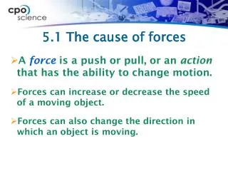
www.ekeeda.com Contact : 9029006464 Res & Comp of Forces Email : care@ekeeda.com P Coplanar Forces Coplanar Forces- -Res & Comp of Forces INTRODUCTION In this chapter we will define the most basic concept in mechanics, the 'Force' and know its various characteristics and effects. We shall further learn to 'break', technically known as 'resolution' of a force and to 'combine' technically known as 'composition' of forces. We shall be studying the different 'systems of forces' and finally we shall learn about 'couples' and their properties. FORCE Force is defined as an agency which changes or tends to change the state of rest or of uniform motion of a body. For example a man trying to push a cupboard as shown in figure (a) exerts a force 'F'. If the force is sufficient to cause motion, the cupboard will slide to the right and if not sufficient, the force F only 'tends' to change the state of rest but not succeeding to cause motion. Similarly Fig. shows an arrangement to bring a rotating wheel to a stop by applying force P to press the brakes. Force is a vector quantity. It is characterised by 1)Magnitude 2)Direction 3)Sense 4)Point of application 1
www.ekeeda.com Contact : 9029006464 Email : care@ekeeda.com For the person pushing the cupboard, refer Fig. (a) and (b) the man applies a force of magnitude F, whose direction is horizontal, sense is to the right and point of application is at C. The S.L unit of force is Newton (N) or its multiples i.e. kilo-Newton (kN), where 1 kN = 1000 N The unit of force has been named after Sir Isaac Newton and one Newton force is defined as a force required producing an acceleration of 1 m/s2 in a body of mass 1 kg. RESOLUTION OF A FORCE Resolution or resolving a force implies breaking the force into components, such that the components combined together would have the same effect as the original force. Fig. (a) Shows a force F acting at an angle 'θ'. This force can be resolved into components F1 and F2 as shown in Fig. (b) or into components Fx, and Fy, as shown in Fig. (c). The components Fx and Fy, of the force F as shown in Fig. (c) are known as the rectangular or perpendicular components of the force, since the two components are perpendicular to each other. Usually we require rectangular components of force and hence let us learn how to find rectangular components of a force. 2
www.ekeeda.com Contact : 9029006464 Email : care@ekeeda.com Resolution of a Force into Rectangular Components Consider a force of magnitude F acting at an angle 0 with the x-axis. Let the force be represented by a line OA drawn to scale. From A drop a perpendicular on the x-axis at E and on the y-axis at P. Length (OE) represents the magnitude of the component along x-axis (Fx) with direction from O to E, while length (OP) represents the magnitude of the component along y-axis ( F ) with direction from O to P. From Geometry Fx= F cos θ → Fy = F sin θ ↑ These are the two rectangular components of force F. SYSTEM OR FORCES System of Forces tell us about how the forces are arranged. For example all the forces may lie on one plane or may lie on different planes. They may meet at a point, may be parallel to each other or may just neither be parallel, nor may meet at a point. 'System' defines this arrangement of forces and is classified as shown. 3
www.ekeeda.com Contact : 9029006464 Email : care@ekeeda.com Coplanar system In this arrangement all the forces lie in one plane. Fig. shows a coplanar system consisting of four forces F1, F2, F3 and F4 all lying in the 'xoy' plane. A coplanar system is further sub-divided into a)Concurrent system: In this system all the forces meet at a point. Examples of concurrent system are, i)A lamp hanging from two strings. If T1 and T2 are the forces developed in the strings and W be the weight of the lamp, then we have a concurrent system at a point A ii)An electric pole supporting heavy electric cables. If F1, F2, F3 are the forces in the cable, and W be the weight of the pole, then the forces form a concurrent system. 4
www.ekeeda.com Contact : 9029006464 Email : care@ekeeda.com b)Parallel system: In this system the lines of action of the forces are parallel. For example; i)A vegetable vendor weighing the vegetables, the weight W1 of vegetables, the measured Weight W2, the force F applied by hand to hold the weighing scale, all three forces form a Parallel system. Refer Fig. (a). ii)Persons sitting on a bench. Fig. (b) Shows three persons of weights P1, P2 and P3 sitting on a bench of self-weight W. If R1 and R2 are the reactions offered by the ground then the six forces form a parallel system. c)General system: Also known as 'non- concurrent and non-parallel' system has forces which do not meet at a single point, nor are parallel to each other. For example the forces acting on the rectangular plate form a general system. Refer Fig. Non-coplanar System When the forces acting in a system do not lie in a single plane, they are termed as Non-coplanar forces or Space forces. Refer Fig. 5
www.ekeeda.com Contact : 9029006464 Email : care@ekeeda.com PRINCIPLE OF TRANSMISSIBILITY OF FORCE It states “A force being a sliding vector continues to act along its line of action and therefore makes no change if it acts from a different point on its line of action on a rigid body”. Consider a rigid body as shown in Fig. acted upon by a force of magnitude F acting at A. The effect on the body would remain unchanged if it acted from point B, C or any other point on its line of action. A practical example explaining Principle of Transmissibility, (Refer fig.(b)) is the case of a locomotive 'L' pulling the wagons „W' to the right by exerting force F from the front. This force gets transmitted to all the wagons and they move forward. The same effect is observed if the locomotive pushes the wagons from behind. Again the force F is transmitted to ail the wagons and they move forward. Transmissibility of force introduces the concept of the force as a Sliding Vector when it acts on rigid body. The force can be shown anywhere on its line of action, causing no change in the force system. MOMENT OF A FORCE We all are aware that a force can cause a body to slide, but at the same time it can cause a body to rotate also. The rotational effect of a force is known as the moment of the force. When we talk of the rotational effect, it has to be with respect to a point. The concerned point is known as the moment centre. The rotational effect of the same force will vary from one moment centre to another and of course if the point (moment centre) lies on the line of action of the force, the moment of force about the point would be zero. The rotational 6
www.ekeeda.com Contact : 9029006464 Email : care@ekeeda.com effect or moment is measured as the product of the force and the perpendicular distance from the moment centre to the force. This perpendicular distance is known as the moment arm „d‟. M= F×d …… 2.1 The tendency to rotate could be either clockwise or anti-clockwise. Fig. shows a force of magnitude F acting on a rectangular plate ABCD as shown. The moment of F about A = F × d1 (anti-clockwise) = + (F × d1) about B = F × d2 (clockwise) = - (F × d2) about C = F × d3 (clockwise) = - (F × d3) about D = O Units of moment are N-m or N-mm or kN-m Sign : we shall take anti-clockwise moments as positive moments, and Convention: clockwise moments as negative. This shall be indicated as + ve. VARIGNON’S THEOREM Varignon, a French mathematician (1654 - 1722) established that the sum of the moments of a concurrent system of forces about any point is equal to the moment of the resultant of the concurrent system about the same point. Though originally derived for a concurrent system of forces, this theorem can in fact be applied to any system of forces and is thus stated as "the algebraic sum of the moments of a system of coplanar forces about and point in the plane is equal to the moment of the resultant force of the system about the same point. 7
www.ekeeda.com Contact : 9029006464 M Email : care@ekeeda.com F R Mathematically it is written as .2.2 = M A A Sum of moments of all forces = Moment of the resultant about the same about any point, say point A. point A. Proof - Let P and O be two concurrent forces 1 and 2 with the x-axis, at O, making angle 1et R be their resultant making an angle 0 with x-axis. Let A be a point on the y-axis about which we shall find the moments of P and Q and also of the resultant R. Let d1, d2 and d be the moment arm of P, Q and R from moment centre A. Let the x component of forces P, Q and R be Px , Qx and Rx respectively Now, Moment of P about A = P = P × d1 …..(1) M A Q = Q × d2 Moment of Q about A = ……(2) M A R Moment of R about A = = R × d M = R (OA cos θ) = OA (Rx) A …..(3) Adding equations (1) and (2) we have P+ Q = P d1 + Q d2 M M A A M F Or sum of moments = (P × OA cos θ1) + ( Q × OA cos θ2) A = OA . Px + OA. Qx since Px= P cos θ1 and Qx = Q cos θ2 = OA ( Px + Qx ) Px + Qx = Rx since the resultant of F M =OA (R ).-----(4) A x forces in the „x‟ direction is the sum of components of Forces in the „x‟ direction Comparing equation (4) with (3) F R M =M -----Proved A A The above equation can similarly be extended for more than two forces in the system. 8
www.ekeeda.com Contact : 9029006464 Email : care@ekeeda.com COMPOSITION OF FORCES (RESULTANT OF FORCES) Composition means to combine the forces acting in a system into a single force, which has the same effect as the number of forces acting together. Such a. single force is known as resultant of the system. Finding the 'resultant' helps to analyse the effect of the forces on the system and may form an important step in the solution of engineering problems. We shall learn to find the resultant of (a) Concurrent system of two forces using law of parallelogram of forces. (b) Concurrent system of more than two forces using method of resolution. (c) Parallel system of forces. (d) General system of forces. Types of Resultant Resultant of a force system may either be a (i) a force or (ii) a couple or (iii) a force couple. Let us understand the three possibilities of a resultant in detail. 1.Resultant- Force In a given force system consisting of number of forces, if on composition of these forces it results in a single force, we call such a resultant as 'Resultant-Force'. Refer Fig. a 2.Resultant – Couple In a force system if the resultant force is zero but the resultant moment is not zero, such a system reduces into a couple. Fig. b shows the 'couple' resultant. Resultant- Couple is possible in a Parallel system or a General force system, but a concurrent force system does not result in a couple. We shall learn in detail about 'couple' later in this chapter. 3.Resultant-Force Couple A resultant force when shifted to a new parallel position without change in its direction and sense, introduces a couple in the system. Such a resultant consisting of a single force and a single couple is called as 'Force Couple'. Fig. c shows a force couple resultant. We shall learn about shifting of a force by introducing of a couple later in this chapter. 9
www.ekeeda.com Contact : 9029006464 Email : care@ekeeda.com RESULTANT OF CONCURRENT SYSTEM OF FORCES USING PARALLELOGRAM LAW OF FORCES Parallelogram law of forces states "If two forces acting simultaneously on a body at a point are represented in magnitude and direction by the two adjacent sides of a parallelogram, then their resultant is represented in magnitude and direction by the diagonal of the parallelogram which passes through the point of intersection of the two sides representing the forces". Let P & Q be the two forces acting at a point and making an angle 'α' with each other as shown in Fig. (a). The forces are drawn to scale in figure such that AB and AD represent forces P & Q. Completing the parallelogram ABCD, the diagonal AC gives the magnitude and direction of the resultant R. Refer Fig. (b). 2 2 Mathematically R = P + Q + 2PQcos a 2.3 (a) Q sina tanθ =P + Qcosa 2.3 (b) Where θ is the angle made by resultant R with the force P Though parallelogram law is for two forces, it can be used for more forces also, but would require repeated use, taking two forces at a time. 10
www.ekeeda.com Contact : 9029006464 Email : care@ekeeda.com RESULTANT OF CONCURRENT SYSTEM OF FORCES USING METHOD OF RESOLUTION When more than two forces act at a point, the use of method of resolution is made to avoid tedious repetition of parallelogram law of forces to successive forces. The following steps are adopted in the solution. Step 1: Resolve the inclined forces if any along the horizontal x direction and the Vertically direction. Step 2:a) Add up the horizontal forces to get ∑Fx. Use sign Convention →+ ve b) Add up the vertical forces to get ∑Fy. Use sign convention ↑ + ve. 2 2 c) The resultant force R= F + F x y Step 3:The direction of the resultant force is the angle θ made by it with the F F y x axis. To find angle θ, use tanθ = x Note: while using the above relation take positive values of and . yF xF The value of θ so obtained will always be less than 90° Step 4: Decide the quadrant of the resultant, depending on the signs of EXERCISE 1 xF and yF 1)Resolve the given forces into horizontal and vertical components. 2)Given F1 = 10 N, F2 = 20 N, F3 = 30 N, F4 = 40 N, F5 = 50 N and taking anticlockwise moment as positive, Find 11
www.ekeeda.com Contact : 9029006464 Email : care@ekeeda.com a)Moment of force F1 about B and E b)Moment of force F2 about A and C c)Moment of force F3 about F d)Moment of force F4 about B and D e)Moment of force F5 about A, F and D. 3)Two forces of 18 N and 35 N act away from a point. If the angle between the forces is 45°, find the magnitude of the resultant and the angle made by it with the 18 N force. 4)Four concurrent forces act at a point as shown. Find their resultant. 5)The striker of carom board lying on the board is being pulled by four players as shown in the figure. The players are sitting exactly at the centre of the four sides. Determine the resultant of forces in magnitude and direction. 6)Find resultant of the force system. 12
www.ekeeda.com Contact : 9029006464 Email : care@ekeeda.com 7)Five concurrent coplanar forces act on a body as shown in figure. Find the force P and Q such that the resultant of the five forces is zero. 8)Figure shows a concurrent system of four forces. Three of the four forces are shown. Find the unknown fourth force „P‟ given that the resultant of the system is a horizontal force of 500 N acting to the right. 13
www.ekeeda.com Contact : 9029006464 Email : care@ekeeda.com RESULTANT OF PARALLEL SYSTEM OF FORCES To find the Resultant of Parallel Force System follow the given steps, Step 1: Since in a parallel system, the forces are directed in one direction only, they can be simply added up using a sign convention for the sense of the force. i.e. R= F Step 2: Location of the resultant force forms an important step. The point of application of the resultant force is found out using Varignon's theorem, discussed earlier in article 2.7. The resultant is initially assumed to act either to the right or left of the reference point at a distance d. F R Varignon's theorem is used. If a positive value of d is M = M A A obtained then the assumption made earlier is true. If a negative value of d is obtained the resultant lies on the opposite side to what was assumed. COUPLE Couple is a special case of parallel forces. Two parallel forces of equal magnitude and opposite sense form a couple. The effect of a couple is to rotate the body on which it acts. Fig. shows a couple formed by two forces of same magnitude F, separated by a distance d known as the arm of the couple. The magnitude of rotation known as the moment of a couple is M = F × d. Rotation of a couple could be clockwise Fig. 2.A (a) or could be anti-clockwise Fig. (b). Couples are represented by curved arrows. Units are N.m, kN.m etc. 14
www.ekeeda.com Contact : 9029006464 Email : care@ekeeda.com PROPERTIES OF COUPLE 1.Couple tend to cause rotation of the body about an axis I to the plane containing the two parallel forces. 2.The magnitude of rotation or moment of a couple is equal to the product of one of the forces and the arm of the couple. 3.Couple is a free vector because of which it can be moved anywhere on the body on which it acts without causing any change. 4.The resultant force of a couple systems is zero. 5.To balance a system whose resultant is a couple, another couple of the same magnitude and opposite sense is required to be added. 6.To shift a force to a new parallel position, a couple is required to be added to the system. For example in Fig. (a), force F is required to be shifted from its original position at A to a new parallel position B. This is done by adding two collinear forces of same magnitude F and - F at B Fig. (b). the two parallel forces F at A and - F at B form a couple. Thus we have a single force F at B and a couple M = F × d in the system Fig. (c). Such a system is called as a force couple system. + ve = + (200 × 7) – (300 × 5) – (150 × 3.5) M D = - 625 Nm = 625 Nm Hence, the system of four forces can be replaced by a single force R : 2OO N t and a couple of 625 Nm ) at D. This is referred to as a force couple system at D. ........Ans. 15
www.ekeeda.com Contact : 9029006464 Email : care@ekeeda.com EXERCISE 2 1)Determine the magnitude and position of the resultant with respect to point A, of the parallel forces shown. 2)Find the magnitude, nature and position of the resultant of the four parallel forces from B. 3)Determine the resultant V of the coplanar parallel forces shown and locate it w.r.t. O. Radius of circle is 2m. 4)A system of parallel, non-concurrent forces is acting on a rigid bar. Reduce this system of forces to i) A single forces R & its position ii) A single force R & a couple at B 5)Find the magnitude of two like parallel forces F1 and F2 acting at a distance of 50 cm apart, if their resultant is 300 N and acts at a distance of 20 cm from one of the force. 16
www.ekeeda.com Contact : 9029006464 Email : care@ekeeda.com 6)Determine the resultant of the parallel forces shown. 7)Determine the resultant of the system shown. 8)Resolve 15 kN force acting at „A‟ into two parallel components at B and C 9)Figure shows a parallel system of four forces and two couples. 1)Replace it by a single force and obtain its location from point A 2)Replace it by a force couple system at point A. 3)Replace it by a force couple system at point D. 4)Replace it by two parallel forces at B and D. RESULTANT OF GENERAL FORCE SYSTEM To find the Resultant of General Force System follow the given steps. Step 1: Follow the same procedure as discussed in article 2.10 and resultant force R of the system using Method of Resolution. Step 2: To locate the position of the resultant follow step 2 of article 2.11. 17
www.ekeeda.com Contact : 9029006464 Email : care@ekeeda.com EXERCISE 3 1)Determine the resultant of the force system shown. The side of each small square is 1 m. The overall size of the body is 4 m × 4 m. 2)Determine the resultant of the given force system. Also find out where the resultant force will meet arm AB. Take A as the origin. 3)a) A system of forces acting on a bell crank lever is as shown. magnitude, direction and the point of application of the resultant w.r.t „O‟. b) Also find the location of the resultant on the horizontal arm of the lever. 4)Find the resultant of the system of coplanar forces shown in figure. Determine the 5)a) A block ABCD of 100 cm × 40 cm dimensions is acted upon by four forces as shown. Calculate the resultant and then state its position with reference to A. b) Also find the location x where the resultant force cuts the base AD. 18
www.ekeeda.com Contact : 9029006464 Email : care@ekeeda.com 6)Determine the resultant of the system of forces shown in figure. Locate the point where the resultant cuts the base AB. 7)Three force 1 kN, 3 kN and 2.5 kN act on a vertical pole 6 m high. a. Find the magnitude, direction and position of resultant w.r.t A b. The position where the resultant cuts the pole from the base c. Reduce it to a force couple system at A. 8)Resolve the system of forces shown into a force and couple at point 'A'. 9)Replace the force system shown by a single force acting at the origin and couple. 19
www.ekeeda.com Contact : 9029006464 Email : care@ekeeda.com 10)Replace the system of forces and couples by a single force and locate the point on the x-axis through which the line of action of the resultant passes. 11)Replace the loading on the frame by a force and moment at point A. 12)Determine the resultant of the given coplanar system of force and a couple. Also locate the resultant on the x axis w.r.t. the origin. Reduce the system to a force couple system at O. 13)A bracket is subjected to a coplanar force system as shown consisting of three forces and couple. If the resultant force of the system is to pass through B, determine the value of the couple M which should be applied at D. 20
www.ekeeda.com Contact : 9029006464 Email : care@ekeeda.com EXERCISE 4 Theory Questions 1)Define i) Force ii) Moment of a force iii) Resultant. 2)illustrate the classification of system of forces with neat sketch. Give one example of each. 3)State the difference between Composition and Resolution of Forces. 4)Give example of i) Coplanar, non-concurrent, non-parallel force system ii) Coplanar, concurrent force system iii) Non coplanar concurrent force system 5)State Varignon's theorem of moments 6)Prove Varignon's theorem of moments. 7)State "Principle of Transmissibility of Force". 8)What is a couple? State its properties. UNIVERSITY QUESTIONS 1.Five concurrent coplanar forces act on a body as shown in figure. Find the forces P and Q such that the resultant of the five forces is zero. (5 marks) 2.Four concurrent forces act at a point as shown. Find their resultant. (4 Marks) 21
www.ekeeda.com Contact : 9029006464 Email : care@ekeeda.com 3.For given system find resultant and its point of application with respect to point O on the X – axis (X intercept). Force, along CA = 100 N, along OD = 250N, along ED = 150 N, along OE = 100 N. An clockwise moment of 5000 N-cm is also acting at the point O. (6 Marks) 4.A ring is pulled by three forces as shown in fig. Find the force F and the angle if resultant of these three forces is 100 N acting in vertical direction. (4 Marks) 5.The resultant of the three forces shown in figure and other two forces Pand Q acting at „A‟ and ‟B‟ is a couple of magnitude 120 kNm clockwise. Determine the force P and Q. (5 Marks) 6.Two concurrent forces P and Q acts such that their resultant acts along x- axis. Determine the magnitude of Q and hence the resultant. (4 Marks) 22
www.ekeeda.com Contact : 9029006464 Email : care@ekeeda.com 7.A system of forces acting on a bell crank is as shown. Determine the magnitude, direction and the point of application of the resultant w.r.t „O‟ (6 Marks) 8.The tension in cable AC is 8 kN. Determine the required tension T in cable AB such that the net effect of the two cable tensions is a downward force at point A. Determine the magnitude R of this downward force. (4 Marks) 9.Discuss the resultant of concurrent forces in space. (4 Marks) 10.A ladder of 4 m length weighing 200 N is placed as shown in Calculate the minimum horizontal force to be applied at 0.25& 0.35 B A A to prevent slipping. (8 Marks) 23