Download
1 / 2
20 likes | 28 Views
Product Code: Series B50 - B52<br>SERIES B50 u2013 ENAMELED CARBON STEEL<br>SERIES B52 u2013 304 STAINLESS STEEL<br>Intake Air Flows to 20,000 CFM B50 u2013 Enameled Steel Construction B52 u2013 304SS 304SS Throat Safety Cages

E N D
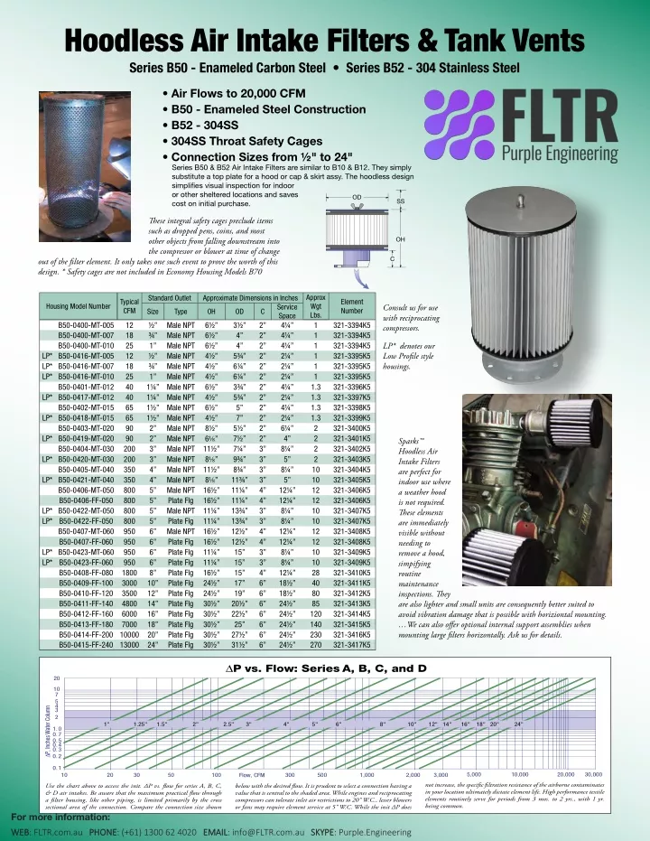
Hoodless Air Intake Filters & Tank Vents Series B50 - Enameled Carbon Steel • Series B52 - 304 Stainless Steel • Air Flows to 20,000 CFM • B50 - Enameled Steel Construction • B52 - 304SS • 304SS Throat Safety Cages • Connection Sizes from 1⁄2" to 24" Series B50 & B52 Air Intake Filters are similar to B10 & B12. They simply substitute a top plate for a hood or cap & skirt assy. The hoodless design simplifies visual inspection for indoor or other sheltered locations and saves cost on initial purchase. �� �� ese integral safety cages preclude items such as dropped pens, coins, and most other objects from falling downstream into the compressor or blower at time of change �� � out of the filter element. It only takes one such event to prove the worth of this design. * Safety cages are not included in Economy Housing Models B70 Approx Wgt Lbs. 1 1 1 1 1 1 1.3 1.3 1.3 1.3 2 2 2 2 10 10 12 12 10 10 12 12 10 10 28 40 80 85 120 140 230 270 Standard Outlet Approximate Dimensions in Inches Typical CFM Element Number Housing Model Number Consult us for use with reciprocating compressors. Service Space 41⁄4” 41⁄4” 41⁄4” 21⁄4” 21⁄4” 21⁄4” 41⁄4” 21⁄4” 41⁄4” 21⁄4” 61⁄4” 4” 81⁄4” 5” 81⁄4” 5” 121⁄4” 121⁄4” 81⁄4” 81⁄4” 121⁄4” 121⁄4” 81⁄4” 81⁄4” 121⁄4” 181⁄2” 181⁄2” 241⁄2” 241⁄2” 241⁄2” 241⁄2” 241⁄2” Size Type OH OD C B50-0400-MT-005 B50-0400-MT-007 B50-0400-MT-010 LP* B50-0416-MT-005 LP* B50-0416-MT-007 LP* B50-0416-MT-010 B50-0401-MT-012 LP* B50-0417-MT-012 B50-0402-MT-015 LP* B50-0418-MT-015 B50-0403-MT-020 LP* B50-0419-MT-020 B50-0404-MT-030 LP* B50-0420-MT-030 B50-0405-MT-040 LP* B50-0421-MT-040 B50-0406-MT-050 B50-0406-FF-050 LP* B50-0422-MT-050 LP* B50-0422-FF-050 B50-0407-MT-060 B50-0407-FF-060 LP* B50-0423-MT-060 LP* B50-0423-FF-060 B50-0408-FF-080 B50-0409-FF-100 B50-0410-FF-120 B50-0411-FF-140 B50-0412-FF-160 B50-0413-FF-180 B50-0414-FF-200 10000 B50-0415-FF-240 13000 12 18 25 12 18 25 40 40 65 65 90 90 200 200 350 350 800 800 800 800 950 950 950 950 1800 3000 3500 4800 6000 7000 1⁄2” 3⁄4” 1” 1⁄2” 3⁄4” 1” 11⁄4” 11⁄4” 11⁄2” 11⁄2” 2” 2” 3” 3” 4” 4” 5” 5” 5” 5” 6” 6” 6” 6” 8” 10” 12” 14” 16” 18” 20” 24” Male NPT Male NPT Male NPT Male NPT Male NPT Male NPT Male NPT Male NPT Male NPT Male NPT Male NPT Male NPT Male NPT Male NPT Male NPT Male NPT Male NPT Plate Flg Male NPT Plate Flg Male NPT Plate Flg Plate Flg Plate Flg Plate Flg Plate Flg Plate Flg Plate Flg Plate Flg Plate Flg Plate Flg Plate Flg 61⁄2” 61⁄2” 61⁄2” 41⁄2” 41⁄2” 41⁄2” 61⁄2” 41⁄2” 61⁄2” 41⁄2” 81⁄2” 61⁄8” 111⁄2” 81⁄8” 111⁄2” 81⁄8” 161⁄2” 161⁄2” 111⁄4” 111⁄4” 161⁄2” 161⁄2” 111⁄4” 111⁄4” 161⁄2” 241⁄2” 241⁄2” 301⁄2” 301⁄2” 301⁄2” 301⁄2” 301⁄2” 31⁄2” 4” 4” 53⁄4” 61⁄4” 61⁄4” 33⁄4” 53⁄4” 5” 7” 51⁄2” 71⁄2” 71⁄4” 93⁄4” 83⁄4” 113⁄4” 111⁄4” 111⁄4” 133⁄4” 133⁄4” 121⁄2” 121⁄2” 15” 15” 15” 17” 19” 201⁄2” 221⁄2” 25” 271⁄2” 311⁄2” 2” 2” 2” 2” 2” 2” 2” 2” 2” 2” 2” 2” 3” 3” 3” 3” 4” 4” 3” 3” 4” 4” 3” 3” 4” 6” 6” 6” 6” 6” 6” 6” 321-3394K5 321-3394K5 321-3394K5 321-3395K5 321-3395K5 321-3395K5 321-3396K5 321-3397K5 321-3398K5 321-3399K5 321-3400K5 321-3401K5 321-3402K5 321-3403K5 321-3404K5 321-3405K5 321-3406K5 321-3406K5 321-3407K5 321-3407K5 321-3408K5 321-3408K5 321-3409K5 321-3409K5 321-3410K5 321-3411K5 321-3412K5 321-3413K5 321-3414K5 321-3415K5 321-3416K5 321-3417K5 LP* denotes our Low Profile style housings. Sparks™ Hoodless Air Intake Filters are perfect for indoor use where a weather hood is not required. ese elements are immediately visible without needing to remove a hood, simpifying routine maintenance inspections. ey are also lighter and small units are consequently better suited to avoid vibration damage that is possible with horiziontal mounting. …We can also offer optional internal support assemblies when mounting large filters horizontally. Ask us for details. ∆P vs. Flow: Series A, B, C, and D 20 10 7 5 43 ∆P, Inches Water Column 2 1" 1.25" 1.5" 2" 2.5" 3" 4" 5" 6" 8" 10" 12" 14" 16" 18" 20" 24" 1.0 0.7 0.5 0.4 0.3 0.2 0.1 5,000 10,000 20,000 30,000 20 30 50 100 300 500 1,000 2,000 3,000 10 Flow, CFM not increase, the specific filtration resistance of the airborne contaminates in your location ultimately dictate element life. High performance textile elements routinely serve for periods from 3 mos. to 2 yrs., with 1 yr. being common. Use the chart above to access the init. ∆P vs. flow for series A, B, C, & D air intakes. Be aware that the maximum practical flow through a filter housing, like other piping, is limited primarily by the cross sectional area of the connection. Compare the connection size shown For more information: below with the desired flow. It is prudent to select a connection having a value that is central to the shaded area. While engines and reciprocating compressors can tolerate inlet air restrictions to 20" W.C., lesser blowers or fans may require element service at 5" W.C. While the init ∆P does WEB WEB: FLTR.com.au PHONE PHONE: (+61) 1300 62 4020 EMAIL EMAIL: info@FLTR.com.au SKYPE SKYPE: Purple.Engineering
Air Intake Filter Choices Model Considerations, Air Flow Sizing, Connection Style Choices, Plate Flange Sizing Your Choice of Connection Types: Filters are available in a wide selection of inlet and outlet sizes and configurations in both enamel finished carbon steel, 304SS, and 316SS. Atmospheric air intake series B10, B12, and B70 with weather hoods can be mounted directly, or piped from a roof top installation to equipment below. In sheltered installations, hoodless air intake series B50 and B52 with exposed filter elements make inspection or pre-filter cleaning a breeze. To silence excess noise at the equipment's inlet, chamber silenced series C10 & C12, or tube silenced series D10 & D12 can cut noise in half. In-line filters E20, E22, & Side Arm Housings F20, & F22 permit installation anywhere between the inlet source and equipment being served. ey're perfect for indoor placement with exterior draws, eliminating the need to climb onto the roof. Models with bolt seal closures serve internal pressures to 5 psid (opt. greater) in air or gas services. e H20, H22 exhaust series can stop most mist and smoke in its tracks, without the ∆P penalty loss of older designs. eir revolutionary radial fin reverse flow design makes it happen. An exclusive removable 304SS perforated steel safety cage guards the housing's throat to eliminate the heart attacks when you drop your hat or the wing nut during change out of the filter element. is cage has been sized with excess open area to avoid pressure loss. If you've ever searched for the wing nut when changing the air filter on your auto, you know first hand just how important a throat guard can be. Standard models have male NPT (MT) or flat face flange (FF) connections. Flanges match the diameter & drilling for 150# ANSI standard. Select optional right angle base (AF) for side mounts, female NPT (FT), bevel (BV) or square cut stub necks (PE) where you wish to weld in place. e right angle connection permits exterior wall mounts with gravity still working on your side to ensure an enduring element seal. For situations where you absolutely positively must go truly on edge, we can provide units for horizontal mount with special interior element side mount support assemblies. Increased or decreased connection sizes are also available on any model. Consult us for other material options. FF - Flat Face Flanges MT - Male NPT FT - Female NPT AF - Right Angle Flange. Bolt Centers Straddle Center Lines. PE - Plain Stub, 90° cut that matchs nominal pipe ODs, or TE - for 90° cut that matchs actual tube ODs. BE - Beveled Stub, 37.5° cut., or as you wish, you designate. See http://www.sparksfilters.com for more options. BC 6 7.5 8.5 9.5 11.75 14.25 17 18.75 21.25 22.75 25 29.5 Hole Bore # Holes Flange 3 4 5 6 8 10 12 14 16 18 20 24 Bore 3.5 4.5 5.6 6.7 8.7 10.88 12.88 14.1 16.1 18.1 20.2 24.2 OD 7.5 0.75 0.75 0.875 0.875 0.875 1 1 1.125 1.125 1.25 1.25 1.375 4 8 8 8 8 12 12 12 16 16 20 20 A 304SS throat safety cage sits beyond the filter element on all but economy housings. is exceptional feature ensures that the handle or pen you drop during change out doesn't fall into the process equipment downstream! And because it's 304SS, it's maintenance free. 10 11 13.5 16 19 21 23.5 25 27.5 3 Bore BC OD Thickness = 3/8" to 1/2" all Data above will assist in matching the flange connection of any existing filter housing(s) in need of replacement. Sparks™ flanges match the diameter & drilling for 150# ANSI standard. Since it is not practical to measure the Bore of an installed unit, wrestle with your not very flexible metal tape to measure a 90° arc (1/4 of the circle, see red line) over the bolts of of your existing flange. Multiply by 4. Count the bolts. Compare with the chart above. Do Not rely upon the more easily measured flange OD for flange sizing as it can vary between suppliers. Wing nuts and sealing washer for easy access. Another small detail that eliminates your need to hunt around for a wrench in order to take a quick look at the filter element. ∆P vs. Flow: Series A, B, C, and D 20 10 7 5 43 ∆P, Inches Water Column 2 1" 1.25" 1.5" 2" 2.5" 3" 4" 5" 6" 8" 10" 12" 14" 16" 18" 20" 24" 1.0 0.7 0.5 0.4 0.3 0.2 0.1 5,000 10,000 20,000 30,000 20 30 50 100 300 500 1,000 2,000 3,000 10 Flow, CFM increase, the specific filtration resistance of the airborne contaminates in your location ultimately dictate element life. High performance textile elements routinely serve for periods from 3 mos. to 2 yrs., with 1 yr. being common. Use the chart above to access the init. ∆P vs. flow for series A, B, C, & D air intakes. Be aware that the maximum practical flow through a filter housing, like other piping, is limited primarily by the cross sectional area of the connection. Compare the connection size shown below with the desired flow. It is prudent to select a connection having a value that is central to the shaded area. While engines and reciprocating compressors can tolerate inlet air restrictions to 20" W.C., lesser blowers or fans may require element service at 5" W.C. While the init ∆P does not For more information: WEB WEB: FLTR.com.au PHONE PHONE: (+61) 1300 62 4020 EMAIL EMAIL: info@FLTR.com.au SKYPE SKYPE: Purple.Engineering