Download

1 / 33
360 likes | 980 Views
SWITCHES. W. C. “Buster” Hounshell Spring 2002. SWITCHES. Control electrical current passing through hot circuit wires Can be wired to control light fixtures, ceiling fans, appliances, and receptacles. WALL-SWITCH BASICS. Wall-switches are available in three general types

E N D
SWITCHES W. C. “Buster” Hounshell Spring 2002
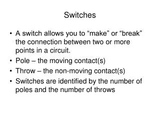
SWITCHES • Control electrical current passing through hot circuit wires • Can be wired to control light fixtures, ceiling fans, appliances, and receptacles
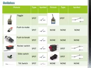
WALL-SWITCH BASICS Wall-switches are available in three general types Single pole switches Three-way switches Four-way switches
WALL SWITCH • A wall switch is connected to circuit wires with screw terminals or with push-in fittings on the back of the switch.
Wall switch strip gauge • A switch may have a stamped strip gauge that indicates how much insulation must be stripped from the circuit wires to make the connections.
Mounting straps • The switch is attached to a metal mounting strap that allows it to be mounted in an electrical box..
Rating stamps • Rating stamps are found on the strap and on the back of the switch. Abbreviations UL or UND. LAB. INC. LIST means that the switch meets the safety standards of the Underwriters Laboratories.
Voltage and amperage ratings • Switches also are stamped with maximum voltage and amperage ratings. Standard wall switches are rated 15A, 125V. Voltage ratings of 110, 120, and 125 are considered to be identical for purposes of identification
Wire gauge rating • For standard wall switch installations, choose a switch that has a wire gauge rating of #12 or #14. For wire systems with solid-core copper wiring, use only switches marked COPPER or CU.
Aluminum wire- warning • For aluminum wiring, use only switches marked CO/ALR. Switches marked AL/CU can no longer be used with aluminum wiring, according to the National Electrical Code.
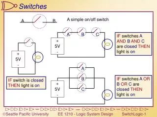
Single-pole Wall Switches • A single-pole switch is the most common type of wall switch. • It usually has ON-OFF markings on the switch lever and is used to control a set of lights, an appliance, or a receptacle from a single location.
Single-pole Wall Switches • A single-pole switch has two screw terminals and a grounding screw.
Single-pole Wall Switches • When installing a single-pole switch, check to make sure the ON marking shows when the switch lever is in the up position.
Single-pole Wall Switches • In a correctly wired single-pole switch, a hot circuit wire is attached to each screw terminal. However, the color and number of wires inside the switch box will vary, depending on the location of the switch along the electrical circuit
Typical Single-pole Switch Installations • Two cables enter the box when a switch is located in the middle of a circuit • Each cable has a white and a black insulated wire, plus a bare copper grounding wire.
Single-pole Switch Installations • The black wires are hot and are connected to the screw terminals on the switch. • The white wires are neutral and are joined together with a wire connector. • Grounding wires are pigtailed to the switch.
One cable entering the box • When a switch is located at the end of a circuit • The cable has a white and a black insulated wire • plus a bare copper grounding wire.
One cable entering the box • In this installation, both of the insulated wires are hot. • The white wire may be labeled with black tape or paint to identify it as a hot wire. • The grounding wire is connected to the switch grounding screw.
Three-way Wall Switches • Three-way switches have three screw terminals and do not have ON-OFF markings. • Three-way switches are always installed in pairs and are used to control a set of lights from two locations.
Three-way Wall Switches • One of the screw terminals on a three-way switch is darker than the others. This screw is the common screw terminal. • The position of the common screw terminal on the switch body may vary, depending on the manufacturer.
Three-way Wall Switches • Before disconnecting a three-way switch, always label the wire that is connected to the common screw terminal. • It must be reconnected to the common screw terminal on the new switch.
Typical Three-way Switch Installations • Two cables enter the box • The switch lies in the middle of a circuit. • One cable has two wires, plus a bare copper grounding wire • The other cable has three wires, plus a ground.
Three-way Switch Installations Two cables entering the box • The black wire from the two-wire cable is connected to the dark, common screw terminal • The red and black wires from the three-wire cable are connected to the traveler screw terminals
Three-way Switch Installations Two cables entering the box • The white neutral wires are joined together with a wire connector • The grounding wires are pigtailed to the grounded metal box.
Typical Three-way Switch Installations One cable enters the box • One cable enters the box • The switch lies at the end of the circuit. • The cable has a black wire, red wire, and white wire, plus a bare copper grounding wire • The black wire must be connected to the com- mon screw terminal, which is darker than the other two screw terminals. The white and red wires are connected to the two traveler screw terminals. The bare copper grounding wire is connected to the grounded metal box.
Three-way Switch Installations One cable enters the box • The black wire must be connected to the com- mon screw terminal, which is darker than the other two screw terminals. • The white and red wires are connected to the two traveler screw terminals • The bare copper grounding wire is connected to the grounded metal box.
Four-way Wall Switches • Four-way switches have four screw terminals • They do not have ON-OFF markings • Four-way switches are always installed between a pair of three-way switches
This switch combination makes it possible to control a set of lights from three or more locations. Four-way switches are common in homes where large rooms contain multiple living areas, such as a kitchen opening into a dining room. Four-way Wall Switches
Typical Installation Four-way Wall Switches • In a typical installation, there will be a pair of three-way cables that enter the box for the four- way switch
Typical Installation Four-way Wall Switches • With most switches, the white and red wires from one cable should be attached to the bottom or top pair of screw terminals
Typical Installation Four-way Wall Switches • The white and red wires from the other cable should be attached to the remaining pair of screw terminals • However, not all switches are configured the same way • Wiring configurations in the box may vary • Always study the wiring diagram that comes with the switch.
Four-way Wall Switches review • Four wires are connected to a four-way switch • The red and white wires from one cable are attached to the top pair of screw terminals • The red and white wires from the other cable are attached to the bottom screw terminals.