Download
1 / 36
410 likes | 938 Views
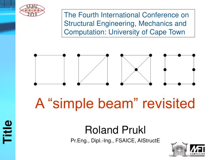
The Fourth International Conference on Structural Engineering, Mechanics and Computation: University of Cape Town. Title. A “simple beam” revisited Roland Prukl Pr.Eng., Dipl.-Ing., FSAICE, AIStructE. Dedicated to Gali Henry Katie. Dedication. Contents Introduction FEMSA ‘92

E N D
The Fourth International Conference on Structural Engineering, Mechanics and Computation: University of Cape Town Title A “simple beam” revisited Roland Prukl Pr.Eng., Dipl.-Ing., FSAICE, AIStructE
Dedicated to Gali Henry Katie Dedication
Contents • Introduction • FEMSA ‘92 • SEMC 2001 • SEMC 2010 - A “simple beam” revisited • Conclusions – SEMC 2010 • SEMC 2013 - Axisymmetric models • Conclusions – SEMC 2013 • Appeal • Acknowledgements Contents
Around 1980 Kamel & McCabe stated: “The finite element method is an approximate method based on discretization of both geometry, loading and boundary conditions, as well as the use of elements derived using various assumptions of which the user is often not quite aware.” Introduction
At about the same time Bathe prophesied: “Within a period of ten years the powerful tool of finite element analysis will be available on every analysis engineer’s desk, but not enough people will be trained sufficiently by then to correctly and safely apply this method.” Introduction
At the FEMSA 1992 Symposium in Cape Town, the author presented: The CST (Constant Strain Triangle) – An insidious survivor from the infancy of FEA The results from various finite element programs, using eight different meshes of plane stress elements, as well as from one boundary element mesh, were compared. FEMSA ‘92
A concrete beam, 8m long, 2m high and 0,2m thick is loaded with a vertical u.d.l. of 100 kN/m at the top. The material properties are: Young’s modulus 3,0e7 kPa and Poisson’s ratio v = 0,2. FEMSA ‘92 The horizontal stresses at the centre of the span should be –6000 kPa (compression) at the top and +6000 kPa (tension) at the bottom.
Four 4-noded quads Eight 3-noded triangles Maximum stress error = 100% FEMSA ‘92 Maximum stress error = 13%
At the SEMC 2001 Symposium in Cape Town, the author presented: Finite Element Analysis (FEA) tests on a simple beam Important Information for users of FEA software. For the same problem as used at FEMSA’92, the results from various finite element programs, using 63 different shell and 23 solid meshes, were compared. SEMC 2001
. SEMC 2001 Using plane stress elements in program Strand7 for this mesh, the maximum stress error at the bottom of the beam at midspan can even be 116 %, i.e. instead of +6000 kPa tension, we get -981 kPa compression !!!
Since 1986, the writer has presented a one-week course “The Application of the Finite Element Method in Practice” about every two months. In almost every course some of the participants, when modelling a simply supported deep beam with shell elements, make the same mistake: They add unnecessary restrained freedoms (translation DZ as well as the rotations RX, RY and RZ) to all node points of the structure. SEMC 2010
SEMC 2010 In the program Strand7, when using 3-dimensional shell elements without any unnecessary restraints at the nodes, the maximum error in a model with four 4-noded elements is 14 %. With DZ, RX, RY & RZ restrained at all nodes, the error increases to 38 %. This error increase is, in fact, caused only by the RZ restraint.
In the program “Prokon Frame” version W2.72, the maximum stress error increases from 5 % to 24 %. In the program Adina, the maximum stress error for both cases (with and without the additional restrained freedoms), is 13 %. SEMC 2010
SEMC 2010 If one uses 8- or 9-noded elements in Strand7, the maximum stress error for both models will be 3 %.
SEMC 2010 Very coarse mesh !
Conclusions SEMC 2010 • Finite Elements have to be handled with great care. • Different programs might give different results and even with the same program the results from different element types might differ considerably from each other. • All structures have to be supported carefully and unnecessary supports must be avoided. Conclusions SEMC 2010
Axisymmetric models A circular slab with radius of 8 m and a thickness of 2 m is simply supportedaround the outer edge and loadedwith a UDL of 500 kPa. The material properties are: Young’s modulus = 3,0e7 kPa andPoisson’s ratio v = 0,2. Axisymmetric models
Axisymmetric models Centre of slab Cross section of circular slab: radius = 8 m, thickness = 2 m The horizontal stresses at midspan should be - 9600 kPa (compression) at the top and + 9600 kPa (tension) at the bottom.
1) 4-noded shells, using program Strand7 Axisymmetric models Maximum stress error at midspan = 0%
2) 8-noded shells, using program Strand7 Axisymmetric models Maximum stress error at midspan = 2%
3) 8-noded solids, using program Strand7 Axisymmetric models Maximum stress error at midspan = 5%
4) 20-noded solids, using program Strand7 Axisymmetric models Maximum stress error at midspan = 2%
5) 8-noded solids, using program Strand7 Axisymmetric models Maximum stress error at midspan = 1%
6) 20-noded solids, using program Strand7 Axisymmetric models Maximum stress error at midspan = 1%
7) 4-noded axisymmetric solids,with no horizontal supports at the centre, using program Strand7 Axisymmetric models Centre of slab Maximum stress error at midspan = 121%
8) 4-noded axisymmetric solids, with horizontal supports at the centre, using program Strand7. Axisymmetric models Centre of slab Maximum stress error at midspan = 93%
9) 4-noded axisymmetric solids, without horizontal supports at the centre, using program Strand7. Axisymmetric models Centre of slab Maximum stress error = 53%
10) 4-noded axisymmetric solids, with horizontal supports at the centre, using program Strand7. Axisymmetric models Centre of slab Maximum stress error = 44%
11) 8-noded axisymmetric solids, without horizontal supports at the centre, using program Strand7. Axisymmetric models Centre of slab Maximum stress error = 2%
12) 8-noded axisymmetric solids, with horizontal supports at the centre, using program Strand7. Axisymmetric models Centre of slab Maximum stress error = 2%
Conclusions SEMC 2013 • Do not use Quad4 elements for axisymmetric analyses in Strand7 because the program subdivides each element into four triangles. • Quad8 elements for axisymmetric analyses in Strand7 are not being subdivided into triangular elements. • Mr. Stewart Morrison carried out 18 test runs for this circular plate.15 of these test runs produced very good results. The 3 others had errors up to 42 %. Conclusions SEMC 2013
Appeal I appeal to all Finite Element users. Please carry out all or some of my tests on the software of your choice and send them to me. I shall then forward you all my detailed information on the subject. Appeal
Final note The purpose of this presentation is to warn users of finite element software about possible pitfalls. The figures produced should not be considered as indicative of these programs for general use. The author wishes to emphasize that the aberrations highlighted are specific to the problems analysed and should not be regarded as his preference for one or the other package compared. Final note
Acknowledgements • The author wishes to thank the following persons who assisted in the preparation of this report: • Mr. Edwin Clarkefor conducting the Strand7 & Prokon analyses • Mr. Steve van Wykfor conducting the Adina and Ansys analyses • Mr. Jurgen van Wykfor conducting the Cosmos analyses • Mr. Stewart Morrisonfor conducting the Lusas analyses • Mr. Adrian Peirsonfor proofreading Acknowledgements
End Thank you for your attention !