Download
1 / 83
880 likes | 978 Views
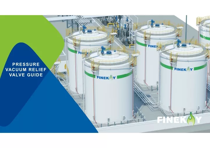
The FINEKAY Pressure/Vacuum Relief Valve Guideuff0ccovers terminology, design, API 2000 specifications, dimensions, installation recommendations, and explosion-proof recommendations.

E N D
TOM 2020 PRESSURE VACUUM RELIEF VALVE GUIDE
CONTENTS A. B. C. D. E. F. G. Terms Design of relief valves API Size Suggestions for installation Suggestions for explosion prevention Summary
A. Terms Pressure / vacuum relief devices Gravity-loaded relief valve: a device driven by inlet static pressure, which will open in an emergency or any abnormal condition to prevent the internal fluid pressure from rising beyond a specified value. The said equipment can also be designed to prevent an excessive internal vacuum. The said device can be a pressure relief device, a non-reclosing pressure relief valve or a vacuum relief valve. Spring-loaded relief valve: a pressure relief device, which will automatically reclose and pre-discharge further fluid flow. Pilot-loaded relief valve: a pressure relief valve, in which the main valve and the auxiliary pressure relief valve are united and the auxiliary pressure relief valve is controlling. Size characteristics of relief devices Actual discharge area: the minimum measured net area, which determines the flow through the valve. Curtain area: the area of a cylindrical or conical outlet between the valve seat surfaces above the nozzle holder resulting from the valve clack lift. Equivalent flow area: the area of the pressure relief valve calculated with a recognized flow formula, equal to the effective discharge area. Nozzle area: the flow area of nozzle cross section under the minimum nozzle diameter. Inlet size: unless otherwise specified, it refers to the nominal pipe size of the valve at the inlet connection. Outlet size: unless otherwise specified, it refers to the nominal pipe size (NPS) of the valve at the outlet connection. Lift: the actual stroke of the valve clack away from the closed position when the valve is releasing pressure.
A. Terms System pressure operating characteristics Maximum allowable pressure (MAWP): the maximum gauge pressure allowed at the top of the finished vessels in its working position at the specified temperature. The maximum allowable working pressure is the pressure basis for setting the pressure relief device to protect the vessel. Maximum allowable vacuum (MAWV): the maximum gauge vacuum degree allowed at the top of the finished vessels in its working position at the specified temperature. The maximum allowable working vacuum is the vacuum basis for setting the pressure relief device to protect the vessel. Accumulation: the pressure increment exceeding the vessel MAWP, expressed in pressure unit or percentage, during release through a pressure relief device. The maximum allowable accumulation is determined on the applicable operation and fire emergency specifications. Overpressure: the pressure increment beyond the set pressure of the relief device, expressed in pressure unit or percentage. When the relief device is set at the maximum allowable working pressure of the vessel and the relief device has no inlet pipe loss, the overpressure is the same as the accumulated pressure. Rated release capacity: the part of the measured relief capacity allowed by applicable codes or regulations to be used as the basis for the applied pressure relief device.
A. Terms Equipment pressure Set pressure: the inlet gauge pressure when the pressure relief valve is set open under the service conditions. Back pressure: the pressure formed at the outlet of a pressure relief device due to pressure in the discharge system. Back pressure equals to the sum of the superimposed back pressure and the built-up back pressure. Built-up back pressure: the pressure increment in the discharge header caused by the flow when the pressure relief device is opened. Superimposed back pressure: the static pressure required at the outlet of the pressure relief device when the pressure relief device is in operation. Superimposed back pressure is produced by pressure from other sources in the discharge system and may be constant or variable. Opening pressure: the static pressure increment at the inlet, at which the valve clack has a measurable lift or the fluid is discharged continuously. Closing pressure: the static pressure value at the inlet when the valve clack contacts the valve seat again or the lift is zero. Leakage rate: the vapor escape when the tank pressure is reached. All the pressure or pressure / vacuum relief equipment will show various leakage rates at the loading pipe end. The American Petroleum Institute issued guidelines in API Bulletin 2521 and API 2000.
What will happen to the vessel when there is any problem with vapor management?
A mass of substances will be released to the environment in case of a problem with low-pressure TANKS
A. Summary When designing a low-pressure tank, it is necessary to consider all the possible causes of overpressure and vacuum as well as the ventilation needs of the tank, and take appropriate protective measures. For various possible overpressure or vacuum cases, different protective measures can be taken to protect the low-pressure tanks. When designing a pressure and vacuum relief system, it is necessary to know about the strengths and weaknesses of each protective measure, and make strategic deployment to highlight the strengths and avoid the weaknesses.
B. Relief system: design Although such tanks operate at low pressure, they, with a larger volume, are facing greater risks than smaller pressure vessels. At the maximum storage capacity, the storage release caused by the missing of the primary containment in a low-pressure tank will lead to horrible consequences.
B. Relief system: design For a tank, its size and shape, loss of product during storage and transportation, color and condition of the surface paint, duration of exposure to direct sunlight every day, and heat input generated by any hot product will impact its internal temperature to a certain degree. The temperature relationship is shown below: DAILY AVERAGE TEMPERATURE RELATIONSHIP BETWEEN ATMOSPHERIC TEMPERATURE AND STORAGE TANNK TEMPERATURE Maximum atmospheric temperature (℃) TANK 15.5 18.3 21.1 23.9 26.7 29.5 32.3 35 37.8 40.6 43.3 46.1 48.9 51.6 Max liquid surface temp 15.5 18.3 21.1 23.9 26.7 29.5 32.3 35.0 37.8 40.6 43.3 46.1 48.9 51.6 Min liquid surface temp 10.0 12.7 15.5 18.3 21.1 23.9 26.7 29.5 32.3 35.0 37.8 40.6 43.3 46.1 Max vapor space temp 37.8 40.6 43.3 46.1 48.9 51.6 54.4 57.2 60.0 62.8 65.6 68.3 71.1 73.9 Min vapor space temp 7.2 10.0 12.7 15.5 18.3 21.1 23.9 26.7 29.5 32.3 35.0 37.8 40.6 43.3
B. Relief system: design Failure causes. NORMAL TEMPERATURE STORAGE TANK No. 1 2 3 4 5 6 7 8 9 10 11 Mixing products with different ingredient s Higher temperature due to heat exchanger failure Higher temperature due to climate change Loss of flow due to discharge treatment system failure Inert gas regulator failure, resulting in regulator normally open Chemic al heat release Vent hole control valve failure Internal explosion / deflagration Liquid into the tank Liquid overfilling OVER PRESSURE Fire Temperature reduction / precipitation due to weather change Endothe rmic chemica l reaction Mixing products with different ingredients Excessive cooling due to heat exchanger failure Liquid removed from the tank Increase d cooling Inert gas regulator failure, resulting in regulator normally closed Discharge treatment system failure Vent hole control valve failure VACUUM / / LOW TEMPERATURE STORAGE TANK No. 1 2 3 Insufficient cooling Pump recirculation causes heat input Evaporation caused by environmental heat input OVER PRESSURE Liquid thermal contraction due to the maximum cooling capacity / / VACUUM
B. Relief system: design After determining the possible causes of tank overpressure and vacuum, the optimal protection strategies should be considered. EMERGENCY RELIE VALVE PRESSURE/VACUUM RELIE VALVE GAS REGULATING VALVE FLAME ARRESTER OIL GAUGE FLOATING ROOF
B. Relief system: design System design: the protective measures should be decided on the control grade. The safety shall be ensured essentially from system design, by changing the pressure or vacuum setting value of the tank.
B. Relief system: design To get the optimal solution, it is necessary to integrate all the pressure control devices correctly and take into account the performance characteristics of each device. Please avoid overlapped setpoints to ensure normal operation! Setpoints shall keep a 20-30% interval!
B. Relief system: valve type Direct load pressure relief valve, vacuum relief valve. DIRECT LOAD PRESSURE/VACUUM RELIE VALVE PRESSURE RELIE VALVE VACUUM RELIE VALVE
B. Relief system: valve type Direct load emergency pressure relief valve, vacuum relief valve. DIRECT LOAD EMERGENCY PRESSURE/VACUUM RELIE VALVE EMERGENCY RELIE VALVE EMERGENCY PRESSURE RELIE VALVE
B. Relief system: valve type All spring-loaded relief valves show some delay in opening and closing. The spring type design is applicable to conditions in which the set pressure value above 1psig. PRESSURE LOAD STRUCTURE WEIGHT LOADING SPRING LOADING PILOT LOADING
B. Relief system: valve type Full lift: the rated capacity is reached when the lift is equal to 25% of the nozzle diameter. In practice, a 40% lift is usually needed at pressures below 15 psi due to flow loss. Proportional lift: the valve disk lift increases proportionally with the increase of the inlet pressure setting value. The lift height of the valve disk is greater than or equal to 1/20. Proportional lift Full lift
B. Relief system: valve type Full lift valve: only 10% higher than the pressure setting value can release all potential energy. It can bring the set pressure closer to the maximum allowable working pressure (MAWP).
B. Relief system: valve type Proportional lift valve: a relief valve that opens to a certain degree steadily relative to the pressure increase. It will not suddenly open within 10% of the lift range when there is no pressure increase. When opened at a pressure not exceeding 10%, such relief valves can achieve the lift required to discharge the mass flow.
B. Relief system: summary Tank pressure relief systems, such as atmospheric pressure / vacuum relief valves and emergency relief valves, can be used as protective measures. However, for a tank filled with hazardous substances, such protective measures can only be regarded as the last ditch against the failure of other protective measures. Secondary containment (weak roof tank) and emergency response are only to mitigate the hazards caused by the absence of a tank pressure relief system. Such controls shall not be regarded as preventive measures. SOFT SEAL METAL SEAL
C. Escape / leakage: background In 1963, the US Congress enacted the Clean Air Act, which has been followed by other industrialized countries soon. According to the data provided by EPA (United States Environmental Protection Agency), the VOC discharged from tanks accounts for a substantial proportion in the oil and gas production industry. As indicated by the Assessment of Methane Emissions from the U.S. Oil and Gas Supply Chain, methane emission is nearly 60% higher than the estimated EPA emission.
C. Escape / leakage: challenge Tank discharge source VOLATILE LIQUID FLASHING DISCONTINUOUS CONTINUOUS VALVE OPEN/TURN OFF VALVE FAILURE
C. Escape / leakage: leakage source Case of tank farm escape repair Tank EBU Oil and gas recovery unit HFS Natural gas production unit Well head
C. Escape / leakage: leakage computation 77% of the leakages are related to the tank (i.e. PVRV, top sampling hole) 13% from the gas production unit (GPU) Leakage location detected in the area (Q2 in 2015 to Q2 in 2016) Tank leakage detected (Q2 in 2015 to Q2 in 2016)
C. Escape / leakage: relief valve design Leakage Usually occurs at 92% - 103% of the set valve pressure. The bubbles first pass through the edge of the valve, but the valve disk does not lift from the valve seat. HERMETICALLY CLOSED PRESSURE VACUUM LEAKAGE RELIEF
C. Escape / leakage: valve disk design The FEP / metal kits made of the best seals of the same kind and highly polished through a special process guarantees excellent sealing performance. And metal / metal kits. SOFT SEAL METAL SEAL
C. Escape / leakage: relief valve design For valves with soft valve clack, very soft materials usually can't be used at pressure above 1 psi. Under higher pressure, the soft valve seat will burst due to aerodynamic deformation. In service, soft valve seats will show higher resistance to particles than metal valve seats. Valves with valve seat shall be used when the working temperature is higher than 260 ℃ or the chemical corrosion is strong enough to corrode the soft sealing material. With Teflon and Kalrez, perfluoroelastomers made from DuPont or FEP (polyether-ether-ketone), the limitation of chemical compatibility is greatly relieved. Teflon Metal Kalrez
C. Escape / leakage: relief valve design The amount of leakage/escape increases with time. The diaphragm elastomer wrinkles due to the mechanical compression. Repair the leakage of the valve disk by cleaning or replacing the diaphragm
C. Escape / leakage: nanoscale seal The improved design and production of valve seats and valve clacks ensures the nanoscale surface roughness and flatness. Surface quality: the multi-stage process (honing, grinding and polishing) ensures the roughness and smoothness of the nanoscale sealing surface. Material processing: surface protection and optimized processing technology run through the whole production process. Measurement technology: optical metrology featuring nanoscale precision
C. Escape / leakage: relief valve design Advantages and limitations of different sealing kits THE DIAPHRAGM/METAL SEAT ADVANTAGE LIMITATIONS Very low set pressure available Very long overflow duration and poor sealing property Simple structure Valve seat easy to freeze and close at low temperature / Set pressure hard to adjust METAL DISC/METAL SEAT ADVANTAGE LIMITATIONS Excellent sealing performance of valve seat before pressure relief Only kick-type available Excellent sealing performance of valve seat after pressure relief Temperature limit: 537 ℃ Remarkable chemical and temperature compatibility Pressure limit: 15 psi Short blowdown can be realized /
C. Escape / leakage: test The assembled valve shall be tested for leakage rate at 75% of the set pressure according to the API requirements. A complete test shall check two trays for leakage under both pressure and vacuum conditions.
C. Escape / leakage: test The leakage rate of a valve depends on the vessel operating pressure and the adjusted valve setting value, which are decided by the type of valve tray sealing system. FINEKAY provides different leakage rates for discharge equipment with different sizes, styles and setting values. Minimum leakage rate of FINEKAY® P/V valve Flange connection FINEKAY® Standard API 2000 7th edition over up to Bubbles per min cm³/min m³/h Bubbles per min cm³/min m³/h 50 100 63 18.9 0.00113 786 236.6 0.01420 100 150 94 28.2 0.00169 786 236.6 0.01420 150 200 125 37.5 0.00225 7866 2360.0 0.14160 200 250 157 47.1 0.00283 7866 2360.0 0.14160 250 300 188 50.4 0.00302 7866 2360.0 0.14160 300 350 220 66.1 0.00396 7866 2360.0 0.14160 350 400 252 75.2 0.00454 7866 2360.0 0.14160 400 500 314 94.2 0.00565 31460 9438.0 0.56628 500 600 376 112.8 0.00677 31460 9438.0 0.56628 at 90% set pressure at 75% set pressure
C. Escape / leakage: summary The integrated design method takes into account the functional characteristics of each pressure control device. Select the suitable devices with sealing function. Upper and lower set pressure of air vent (set pressure and set vacuum) Temperature difference in the vapor space of a tank Hydrocarbon concentration in hydrocarbon / air mixture Implement site-wide leakage detection and repair procedure (LDAR) Carry out regular maintenance as recommended by the manufacturer.
C. Escape / leakage: benefit A little medium is discharged into the atmosphere, which mitigates the pollution to the environment and reduces the use of closed sewage system. The medium loss is reduced by more than 50%, lowering the cost greatly. The medium loss is reduced to only several square meters per year (depending on the pressure and specifications of the relief valve) The equipment efficiency is enhanced.
Summary The American Petroleum Institute bulletin discusses in detail the various kinds of escape losses that constitute the total amount of escape losses and offers remedial suggestions. The escape losses discussed in this report can be reduced by proper selection, installation and maintenance of pressure / vacuum relief valves. API Bulletin 2512: Interim Measurement Method for Evaporation Loss from Oil Tanks and Transportation Equipment API Bulletin 2513: Evaporation Loss in the Petroleum Industry - Causes and Control API Bulletin 2514: Evaporation Loss From Tank Cars, Tank Trucks, and Marine Vessels API Bulletin 2515: Use of Plastic Foam to Reduce Evaporation Loss API Bulletin 2516: Evaporation Loss from Low-Pressure Tanks API Bulletin 2517: Evaporation Loss from Floating-roof Tanks API Bulletin 2518: Evaporation Loss from Fixed-roof Tanks API Bulletin 2519: Use of Inner Floating Roof for Fixed-roof Tanks to Reduce Evaporation Loss API Bulletin 2520: Use of Variable Vapor Space System to Reduce Evaporation Loss API Bulletin 2521: Use of Pressure-vacuum Vent Valves for Atmospheric Pressure Tanks to Reduce Evaporation Loss
D. API standard International Organization for Standardization (ISO) has adopted a similar standard system for tank design. These standards have been unified with the API standards. The current ISO 28300 standard for tank venting has become the same as the API 2000 standard. Standard for pressure vacuum relief valve API 2521: Use of Pressure-vacuum Vent Valves for Atmospheric Pressure Tanks to Reduce Evaporation Loss. API STD 2000: Venting Atmospheric and Low-pressure Storage Tanks ISO 28300: Petroleum, Petrochemical and Natural Gas Industries - Venting of Atmospheric and Low-pressure Storage Tanks
D. API standard Air vent determination procedures in ISO 28300, EN14015 and the latest API 2000 7thEdition can keep low-pressure and atmospheric tanks free from atmospheric change impact. STANDARD PROJECT API STD 2000 EN 14015 ISO 28300 PRESSURE/VACUUM SETTING RANGE Full vacuum to 1.034 barg -20 mbar to 500 mbar Full vacuum to 1.034 barg Overground tanks for liquid petroleum or petroleum products and overground and underground refrigerated tanks, with fixed roof Overground tanks for liquid petroleum or petroleum products and overground and underground refrigerated tanks, with fixed roof Non-refrigerated water tank with TANK TYPE fixed roof (with or without internal floating roof) Unlimited tank capacity Unlimited tank capacity Tank volume: 28,618m3, not consider the insulation coefficient of regular venting (only for emergency) TANK CAPACITY Consider insulation for regular Consider insulation for regular and and emergency ventilation emergency ventilation
D. API standard Comments API STD 2000 and ISO 28300 / EN 14015 show a slight difference in outbreathing rate. Either of the two standards can be used to estimate the outbreathing volume.
D. API standard When choosing the pressure / vacuum relief valve (according to API STD 2000), the following parameters should be considered: A.Normal relief: the sum of vapor discharge caused by filling, hot discharge or emptying of a gas tank and hot air intake of a gas tank B.Emergency relief: thermal diffusion due to exposure to external fire Pressure / vacuum relief valve setting (pursuant to API 2521): the pressure / vacuum valve on the atmospheric fixed roof box is usually set as ½oz / in2 (22mm WG) in pressure or vacuum. The test data show that the increase of the pressure setpoint by 1oz / in2 to above 1/2 oz / in2 can reduce the breathing loss by about 7%. However, it is also indicated that the breathing loss decreases gradually with the increase of pressure setpoint by each 1oz / in2. Pressure / vacuum relief valve setting (pursuant to API 2513): the pressure and vacuum settings of a relief valve depend on the structural characteristics of a gas tank. The setting shall refer to API 650, API 620, EN 14015 and shall be within the safe operating range.
D. API standard API STD 2000 Differences between the fifth, sixth and seventh editions of American Petroleum Institute standards. API STD 2000: 5thEdition API STD 2000: 6thEdition API STD 2000: 7thEdition (Annex A = API 5thEdition) (Annex A = API 5thEdition) • Tank volume • Tank volume • Little changes to calculation • Liquid flow (pump-in / pump-out) • Liquid flow (pump in / pump out) • For volatile liquids, the outbreathing volume is • Temperature change • Pump-out only doubled • Pressure control of hydrocarbon in low- • Temperature change • No need to calculate the evaporation rate • Average storage temperature pressure tanks • And industrial tanks • Vapor pressure • Latitude • Alcohol (newly added key item) • High vapor pressure • The flow rate can be doubled (thermal vacuum changes greatly)
D. API standard Both the 6thand 7theditions of API STD 2000 include new variables related to latitude calculation. Major latitude ranges include "below 42°", "between 42° and 58°" and "above 58°". In these latitude ranges, climate changes will cause significant differences in tank pressures. As shown in the table below, coefficient C is related to, in addition to latitude, vapor pressure and average storage temperature. Using coefficient C to calculate the inbreathing flow is necessary for adjusting the size of nitrogen seal regulator of tanks. On the other hand, coefficient Y is only related to latitude and is needed to adjust the vapor recovery regulator when calculating the outbreathing volume. Coefficient C Vapor pressure higher than hexane or unknown Vapor pressure similar to hexane Coefficie nt Y 0.32 Average storage temperature >77°F 6.5 Latitude <77°F 4 <77°F 6.5 >77°F 6.5 Below 42° Between 42° and 58° Above 58° 0.25 3 5 5 5 0.20 2.5 4 4 4 API STD 2000 7th
D. API standard Coefficients C and Y Tank nitrogen seal regulator size calculation: size calculation, starting from inbreathing, will limit the flow demand of a tank nitrogen seal regulator. General steps include: (1) Determine the volume flow needed to replace the pumped liquid; (2) Determine the volume flow needed for a temperature drop; (3) Add the results of (1) and (2). Tank nitrogen seal regulator flow = maximum pump-out rate + temperature drop = [8.02 * maximum pump-out rate] + [3.08 * coefficient C * (tank volume) 0.7 * insulation coefficient]
D. API standard Summary The latest modifications to the previous edition. However, it is important to know that the modifications made in the 6thEdition remain unchanged. Although the 5thEdition is still widely applied to size adjustment of gas regulating valves and vapor recovery regulators, it is expected that the new edition will be more easily accepted and applied in the coming years. (7th API STD 2000 Edition) makes minor
D. API standard - tanks STORAGE TANK STANDARD Specification for the design and manufacture of overground weldable steel tanks that are flat bottomed, vertical, cylindrical, or field constructed for liquid storage at or above room temperature. EN 14015 API 650 Design and construction of large low-pressure welded tanks API 620 Welded steel tanks for oil storage
E. Sizing: thermal breathing The following conditions should be considered to determine the air discharge requirements equivalent to API 2000: 1. In-tank inbreathing - vacuum relief: A: Air flows into the tank due to the liquid outflow during emptying. B: Heat inbreathing is caused by the cooling effect (condensation or condensation) of the atmosphere on the vapor in the tank. 2. In-tank outbreathing - pressure relief: A: Air flows out from the tank due to the liquid inflow during filling. B: Heat release is caused by the heating effect (expansion) of the atmosphere on the vapor in the tank. C: Maximum flow from tank cover valve, if not fully open.
E. Sizing: thermal breathing API 2000: valve sizing (air) If the required discharge rate is determined or given by the customer, the following calculation should be made to determine the valve discharge area needed. VALVE SIZING FORMULA FORMULA WHERE VREQ: latitude factor T: absolute inlet temperature P1: absolute inlet pressure at 100% overpressure of 2PS Z: compressibility of medium P2: absolute outlet pressure A: calculated runner area k: specific heat ratio of experimental medium K: molecular weight of medium K: rated relief coefficient C: overpressure correction coefficient*