Download
1 / 8
0 likes | 6 Views
We are structure and supports Manufacturer, structure and-supports supplier, structure and-supports provider, structure and-supports in Canada

E N D
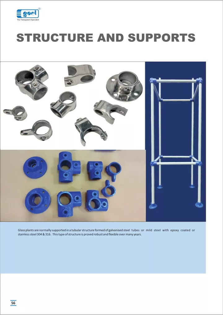
R The Transparent Specialist STRUCTURE AND SUPPORTS Glass plants are normally supported in a tubularstructure formed of galvanised steel tubes or mild steel with epoxy coated or stainless steel 304 & 316. This type of structure is proved robust and flexible over many years. 56
R STRUCTURE AND SUPPORTS SUPPORT OF COLUMN The Transparent Specialist Glass plants and pipeline should be supported correctly. To prevent inducing undesirable stresses in the glass, support should be rigid. When supported, glass should be in compression. Generally, glass plant and equipment are supported in a rectangular tubular structure. This structure is formed of galvenised mild steel tubing with the cast iron fittings which are described in this catalogue. This type of structure provides enough flexibility for future modifications and is strong enough to support a glass unit. GUIDE SUPPORT BRACING IN WALL Following rules should be followed while supporting a glass unit in a tubular structure. 1. The structure must be rigid. To give lateral support it must be braced back to the nearest wall or any rigid feature. 2. All glass columns are build up from a fixed point on which whole weight of the column should be taken. GUIDE SUPPORT 3. With change in temperature, glass column and tubular structure expands at different rate. Therefore glass unit must be free for vertical movement above the fixed point. Hence, above the fixed point, guides supports should be used to give lateral support. BASE SUPPORT FOUNDATION STRUCTURE TUBES, GALVANISED Tube size For forming the structure,"B" class galvanised tubes, Mild Steel with Epoxy Coated, Stainless Steel 304 & 316 are used in size of 1/2", 1", 1.1/4", 1.1/2" and 2". Cut tubes are available in required length to form a standard size structure. Cut tubes are provided with rubber plug at both the ends. Inches 1/2" 1" 1.1/4" 1.1/2" 2" NB NB mm 15 25 30 40 50 External Diameter 19.5 32.5 41.5 48.3 60.3 Available cut lengths Structure NB (mm) Dimension 15* 25* 30* 40* 50* For Vertical installation 2500 3000 3500 4000 6000 - - - - - 2500 3000 3500 - 6000 - - - - - - - - - 3000 3500 4000 6000 6000 6000 TUBE LENGTH For Frames 400 500 600 800 1000 1200 1500 - - - - - - - 365 465 565 765 965 1165 1465 355 455 555 755 955 1155 1455 345 445 545 745 945 1145 1445 335 435 535 735 935 1135 1435 STRUCTURE DIMENSION Cat. Ref. TBG (NBmm/Cut length) for e.g. TBG 25/365 For Support 1000 1200 400 500 600 800 450 550 650 850 1050 1250 450 550 650 850 1050 1250 450 550 650 850 1050 1250 57
R STRUCTURE AND SUPPORTS The Transparent Specialist STRUCTURE FITTINGS NB Following structure fittings are available to use with galvanised tubes in order to form a tubular structure for a glass plant. These fittings are made of cast iron. Also available in Stainless Steel 304 & 316 and are suitable to the galvanised tubes described earlier. d These slidable fittings are provided with grub screws to fix it at required position on a galvanised tube. These fittings are specially made to construct a tubular structure which provides enough flexibility for future modifications without involving any hammering and welding. I D OD STRUCTURE FITTINGS - GENERAL DATA NB TUBE DIA ID OD d 25 30 40 50 32.5 42.5 48.3 60.3 35 45 51 63 45 55 61 73 1/2" 1/2" 1/2" 1/2” STRUCTURE FITTINGS - BASE NB These are to be used with vertical tubes. Holes are provided for foundation. H d Cat.Ref. NB D H PCD dØ BS25* BS30* BS40 BS50 25 30 40 50 150 150 150 175 75 75 75 75 110 110 110 125 4 x 14Ø 4 x 14Ø 4 x 14Ø 4 x 14Ø PCD D STRUCTURE FITTINGS - COUPLER NB These are generally used to couple the vertical tubes where more length is require. Cat.Ref. NB H H1 CL25 CL30 CL40 CL50 25 30 40 50 150 150 150 150 200 200 200 200 H H1 STRUCTURE FITTINGS - BEND These are used to build frames on vertical tubes. NB Cat.Ref. NB H L L NB BN 25* BN30* BN40 BN50 25 30 40 50 55 65 70 85 55 70 80 95 H NB L * marked items are available fast. 58
R STRUCTURE AND SUPPORTS The Transparent Specialist STRUCTURE FITTINGS - TEE Cat.Ref. NB H L NB T25* T30* T40 T50 25 30 40 50 50 65 70 85 55 70 80 95 NB H L STRUCTURE FITTINGS - DOUBLE BEND NB Cat.Ref. NB H L NB H DBN 25 DBN30 DBN40 DBN50 25 30 40 50 55 65 70 85 55 70 80 95 NB NB NB H H L STRUCTURE FITTINGS - DOUBLE TEE NB NB Cat.Ref. NB H L NB H DT25 DT30 DT40 DT50 25 30 40 50 50 65 70 85 55 70 80 95 L L STRUCTURE FITTINGS - EQUAL BRACKET Cat.Ref. NB H L L1 NB1 EBT25* EBT30* EBT40 EBT50 25 30 40 50 45 55 60 70 65 80 85 95 50 55 60 60 H NB L L1 STRUCTURE FITTINGS - UNEQUAL BRACKET Cat.Ref. NB NB1 H L L1 NB1 UBT25/15* UBT30/15* UBT40/25 UBT50/25 25 30 40 50 15 15 25 25 40 50 55 60 65 75 85 95 50 60 60 65 H NB L L1 STRUCTURE FITTINGS - CROSS NB Cat.Ref. NB H L X25 X30 X40 X50 25 30 40 50 50 65 65 65 45 55 70 85 H L 59
R STRUCTURE AND SUPPORTS The Transparent Specialist STRUCTURE FITTINGS - SUPPORT NB Cat.Ref. NB h L d SPT15* SPT25* SPT30* SPT40 SPT50 15 25 30 40 50 30 40 45 50 55 35 50 57 62 67 13 13 13 13 13 H d L STRUCTURE FITTINGS - PLUGS These are used to plug the open ends of galvanised tubes. NB Cat. Ref. NB PLUG15* PLUG25* PLUG30* PLUG40 PLUG59 15 25 30 40 50 STRUCTURE FITTINGS - STUDS These are used as screwed rods with supports Cat.Ref. d L L STUD5/16-150* STUD3/8-150* STUD1/2-200 5/16” 3/8” 1/2” 150 150 200 d STRUCTURE DIMENSIONS FOR COLUMNS DN 80 100 150 225 300 400 450 600 Recommended tube size NB (mm) 25 25 25,30 30 30 30 30,40 40,50 Minimum Structure size Depth X Width 500 x 500 500 x 500 600 x 600 800 x 800 800 x 800 1000 x 1000 1000 x 1000 1200 x 1200 DEPTH WIDTH FOR VESSELS (IN HEATING MENTLES) DEPTH Recommended tube size NB (mm) Minimum Structure size Depth X Width Size (Litres) WIDTH 20 50 100 200 25 25 400 x 600 600 x 800 800 x 800 800 x 1000 25,30 30 * marked items are available fast. 60
R STRUCTURE AND SUPPORTS The Transparent Specialist FOR VESSELS (IN HEATING BATHS) Recommended tube size NB (mm) 25 25 25,30 30 Minimum Structure size Depth X Width 500 x 600 600 x 800 800 x 1000 800 x 1200 DEPTH Size (Litres) 20 50 100 200 WIDTH FOR VESSELS (IN VESSEL HOLDERS) Recommended tube size NB (mm) 25 25 25,30 30 Minimum Structure size Depth X Width 500 x 600 600 x 800 1000 x 1000 1000 x 1000 Size (Litres) 20 50 100 200 DEPTH WIDTH COLUMN BASE SUPPORT FRAMES These channel frames are used as fixed support in erection of columns. These are supplied with full threaded jacking rods and U bolts. PCD L L1 Cat.Ref. PCD L1 L H FCSH225 FCSH300 FCSH400 FCSH450 FCSH600 310 395 495 585 710 1000 1000 1200 1200 1400 800 800 1000 1000 1200 75 75 75 100 100 H 61
R STRUCTURE AND SUPPORTS The Transparent Specialist GROUTING OF BASE 1. Take one Cast Iron BASE and four foundation Bolts, each with 2 nuts. 2. Fit the bolts in BASE so that base is raised upto 150mm from head of bolts. 3. Put this assembly on the floor and prepare a rough surface for proper bonding of grouting. 4. Make a concrete block over the bolts of about 200 x 200 mm upto the base of BASE i.e. 150mm high. 5. Prepare separate block for each BASE instead of making one big common block. For all BASES. 62
R STRUCTURE AND SUPPORTS The Transparent Specialist ASSEMBLING OF STRUCTURE Mark the position of required fittings on all the Vertical tubes, slide them in correct sequence and lightly Tighten. Assemble one side frame of the structure by adding the cross tubes between two vertical tubes. 1 2 Assemble other side frame of the structure by adding the cross tubes between other two vertical tubes. Build up the cross tubes in one side frame and Tighten lightly. 3 4 Add the other side frame on it and tighten all the fittings firmly. Hoist the structure and brace it to some existing rigid feature. 5 6 Grout the foundation bolts and fix the structure bases with that. Adjust bracing to obtain a correct plumb in Structure. 7 8 Assemble the support tubes at their positions. Adjust the horizonatal frames in correct level. 9 10 63