Download
1 / 36
360 likes | 369 Views
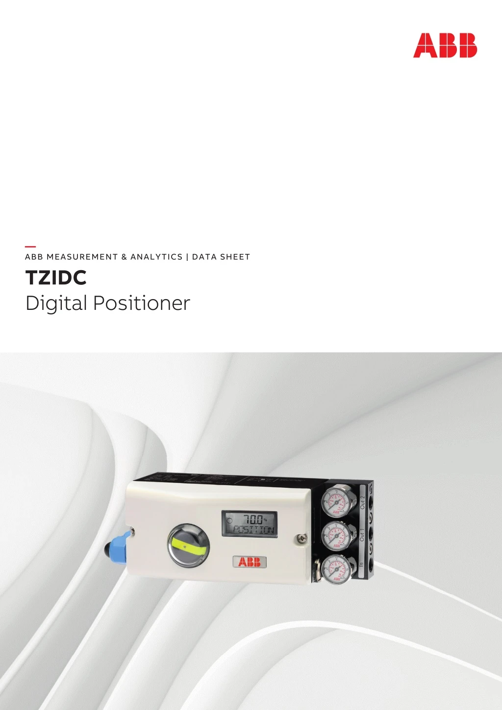
"The TZIDC is an electronically configurable positioner with communication capabilities designed for mounting on pneumatic linear or rotary actuators. It features a small and compact design, a modular construction, and an excellent cost-performance ratio.<br><br>Fully automatic determination of the control parameters and adaptation to the positioner allow for considerable time savings as well as optimum control behavior."<br>For More Information visit on our website:- www.instronline.com<br>Our E-mail Address:-info@instronline.com <br>

E N D
— ABB MEASUREMENT & ANALYTICS | DATA SHEET TZIDC Digital Positioner
2 TZIDC DIGITAL POSITIONER | DS/TZIDC-EN REV. C — For highly accurate and reliable positioning of valves in all sectors — Easy Set-up • Automatic adjustment function • Straightforward initialization — Wide temperature range • ?40 to 85 °C (?40 to 185 °F) — HART Communication — Control Adaptive function • Automatic adjustment of control parameters during operation — Increased shock and vibration resistance • Gearless sensor activation — Fail Save and Fail Freeze function • Selectable safety position of the fitting — Low air consumption • Highly efficient I/P converter
TZIDC DIGITAL POSITIONER | DS/TZIDC-EN REV. C 3 Change from one to two columns Use The positioner has a built-in operating panel providing a 2- line LCD indicator and 4 operating buttons for commissioning, configuration and monitoring during live operation. Alternatively, the appropriate configuration program can be used via the available communication interface. Communication The positioner has a local communication interface (LCI) as standard. Additionally, a ‘HART® communication’ option for communication via the 20 mA signal is available. Both communications are based on the HART® Protocol. Alternatively, HART®5 or HART®7 are available. Inputs / Outputs In addition to its input for the analog position setpoint, the positioner is equipped with a digital input which can be used to activate control system functions in the device. A digital output allows you to output collective messages (alarms / faults). Modular design The basic model can be enhanced at any time by retrofitting optional equipment. Option modules can be installed for analog and digital position feedback. Additionally, a mechanical position indicator, proximity switches or 24 V microswitches are available for indicating the position independently of the mother board function. — Brief description The TZIDC is an electronically configurable positioner with communication capabilities designed for mounting on pneumatic linear or rotary actuators. It features a small and compact design, a modular construction, and an excellent cost-performance ratio. Fully automatic determination of the control parameters and adaptation to the positioner allow for considerable time savings as well as optimum control behavior. Pneumatics An I/P module with subsequent pneumatic amplifier is used to control the pneumatic actuator. The well-proven I/P module proportionally converts the permanent electrical setpoint signal from the CPU into a pneumatic signal used to adjust a 3/3-way valve. Dosing of the air flow for pressurizing or depressurizing the actuator is continuously adjusted. As a result, excellent control results are achieved. When reaching the setpoint, the 3/3-way valve is closed in center position to minimize the air consumption. The pneumatic system can be supplied in four versions: for single acting and double acting actuators and each with the ‘fail-safe’ / ‘fail-freeze’ safety function. ‘Fail-safe’ safety function If the electric power supply fails, the positioner output 1 is depressurized and the return spring in the pneumatic actuator moves the valve to the safe position. In case of a ‘double-acting’ version, output 2 is additionally pressurized. ‘Fail-freeze’ function If the electric power supply fails, the positioner Output 1 (and Output 2 if applicable) is closed and the pneumatic actuator blocks the valve in the current position. If the compressed air supply power fails, the positioner depressurizes the actuator. Change from two to one column
4 TZIDC DIGITAL POSITIONER | DS/TZIDC-EN REV. C — … Brief description Schematic diagram Basic device Optional upgrades 1 LCI plug 2 Setpoint signal 4 to 20 mA 3 Binary input 4 Binary output 5 Supply air: 1.4 to 6 bar (20 to 90 psi) 6 Exhaust 7 I/P module with 3/3-way valve 8 Position sensor 9 Plug-in module analog feedback (4 to 20 mA) 0 Plug-in module digital feedback k Installation kit for mechanical position indication l Limit value monitor with proximity switches m Limit value monitor with 24 V-microswitches Figure 1: Schematic diagram of the positioner Note With optional extensions, either the ‘Limit value monitor with proximity switches’ l or the ‘Limit value monitor with 24 V- microswitches’ m can be used. In both cases though, the mechanical position indication k must be installed. Change from one to two columns
TZIDC DIGITAL POSITIONER | DS/TZIDC-EN REV. C 5 Integral mounting to control valves The positioner featuring standard pneumatic action is available as an option for integral mounting. The required holes are found at the back of the device. The advantage of integrated mounting is that the point for mechanical stroke measurement is protected and that the positioner and actuator are linked internally. No external tubing is required. — Mounting versions Standardized mounting on pneumatic linear actuators Lateral attachment is in accordance with DIN / IEC 534 (lateral attachment to NAMUR). The required attachment kit is a complete set of attachment material, but does not include the pipe fittings and air pipes. 1 2 M11023 M11021 Figure 4: Integral mounting on control valves 1 Columnar yoke 2 Cast iron yoke Figure 2: Mounting on linear actuators in accordance with DIN / IEC 534 Standardized mounting on pneumatic rotary actuators This attachment is designed for mounting according to the standard VDI / VDE 3845. The attachment kit consists of a console with mounting screws for mounting on a rotary actuator. The corresponding feedback shaft adapter has to be ordered separately. Screwed pipe connections and air pipes have to be provided on site. M11024 Figure 5: Integral mounting on control valves with adapter plate Special actuator-specific mounting versions In addition to the mounting methods described above, there are special actuator-specific attachments. M11022 Figure 3: Mounting on rotary actuators in accordance with VDI / VDE 3845
6 TZIDC DIGITAL POSITIONER | DS/TZIDC-EN REV. C Note To connect the TZIDC Remote Sensor, a cable with the following specifications needs to be used: • 3-wire, cross-section 0.5 to 1.0 mm² • shielded, with at least 85 % coverage • Temperature range up to at least 100 °C (212 °F) The cable glands must also be approved for a temperature range up to at least 100 °C (212 °F). The cable glands require a mounting for the shielding and strain relief for the cable in addition. ABB optionally offers a cable gland and cable for the TZIDC Remote Version. B In this version the positioner is supplied without a position sensor. The following points should be observed during installation: • Housing 1 (TZIDC Control Unit) contains the electronics and pneumatics and is mounted separately from the actuator. • The remote position sensor is mounted on the linear and rotary actuator. Follow the operating instructions for the remote position sensor for mechanical mounting! — … Mounting versions External position sensors A 1 2 3 6 5 4 B 1 2 7 6 5 4 M10904 B TZIDC Control Unit for remote position sensor 1 TZIDC Control Unit 2 Connection cable 3 TZIDC Remote Sensor 4 Actuator 5 Compressed air supply 6 Set point signal 7 Remote position sensor Figure 6: TZIDC with external position sensors Note If the device is being operated on a cylinder, for reasons associated with linearity you should run the Auto Adjust function for rotary actuators A In this version, the components are supplied in two housings, which together form one harmonized unit. The following points should be observed during installation: • Housing 1 (TZIDC Control Unit) contains the electronics and pneumatics and is mounted separately from the actuator. • Housing 2 (TZIDC Remote Sensor) contains the position sensor and is mounted on the linear and rotary actuator. * The TZIDC Remote Version is temporarily not available for the marine version. A TZIDC Control Unit with TZIDC Remote Sensor*
TZIDC DIGITAL POSITIONER | DS/TZIDC-EN REV. C 7 Shut-off function This parameter can be set separately for each end position. When the associated limit value is up-scaled, the function causes immediate travel of the actuator to the selected end position. If the value ‘0’ is entered for the corresponding parameter, the position is further controlled, even in the respective end position. Actuator travel time prolongation This function can be used to increase the max. travel time for full travel. This time parameter can be set separately for each direction. This function can only be used with the pneumatics with the safety function ‘fail-safe’. Switching points for the position You can use these parameters to define two position limit values for signaling, see option ‘Module for digital position feedback’. Digital output The alarms generated in the positioner can be polled via the digital output as a collective alarm. The desired information can be selected via the operator panel or remotely via the configuration program. The output can be set to ‘active high’ or ‘active low’, as required. Digital input For the digital input, one of the following safety options can be selected. You may use the operator’s panel or configuration program to select an option. • No function (standard setting) • Move to position 0 % • Move to position 100 % • Hold previous position • Block local parameterization • Block local parameterization and operation • Block all access (no local or remote access via a PC) The selected function is activated when the 24 V signal is no longer connected to the digital input (< 11 V DC). — Device parameters General Microprocessor-based position control in the positioner optimizes control. The positioner features high-precision control functions and high operational reliability. Due to their elaborate structure and easy accessibility, the device parameters can be quickly adapted to the respective application. The total range of parameters includes: • Operating parameters • Adjustment parameters • Operation monitoring parameters • Diagnosis parameters • Maintenance parameters Operating parameters The following operating parameters can be set manually if required: Setpoint signal 0 to 100 % freely selectable for split-range operation For 4 to 20 mA and HART version: • Signal min. 4 mA, max. 20 mA (0 to 100 %) • Minimum range 20 % (3.2 mA) • Recommended range > 50 % (8.0 mA) Action (set point signal) Increasing: • Position value 0 to 100 % = direction 0 to 100 % Decreasing: • Setpoint signal 100 to 0 % = direction 0 to 100 % Characteristic curve (actuator travel = f {set point signal}) Linear, equal percentage 1:25 or 1:50 or 25:1 or 50:1 or freely configurable with 20 reference points. Actuator travel limit The actuator travel, i.e. the stroke or angle of rotation, can be reduced as needed within the full range of 0 to 100 %, provided that a minimum value of 20 % is observed.
8 TZIDC DIGITAL POSITIONER | DS/TZIDC-EN REV. C — … Device parameters Diagnosis parameters Adjustment parameters The diagnostics parameters in the positioner's operating program provide information about the operating conditions of the valve. From this information the operator can derive what maintenance work is required, and when. Additionally, limit values can be defined for these parameters. When they are exceeded, an alarm is reported. So, for example, the following operating values are determined: • Number of movements of the final control element • Sum of individual actuator travel events The diagnosis parameters and limit values can be called up, set, and reset via HART communication, using the configuration program. The positioner has a special function for automatic adjustment of the parameters. Additionally, the control parameters can be set automatically (in adaptive control mode) or manually to optimally adapt them to the process requirements. Tolerance band Upon reaching the tolerance band, the position is re-adjusted more slowly until the dead band has been reached. Dead band (sensitivity) When reaching the dead band, the position is held. The factory setting for this parameter is 0,1 %. Actuator spring action Selection of the direction of rotation of the sensor shaft (looking at the open housing), if the safe position is approached as a result of the spring force in the actuator (actuator is depressurized via Y1 / OUT1). For double-acting actuators, the actuator spring action corresponds to pressurizing the pneumatic output (Y2 / OUT2). Display 0 to 100 % Adjust the display 0 to 100 % in accordance with the direction for opening or closing the final control element. Operator panel The integrated operating panel of the positioner has four operating buttons which allow the device to be operated with an open housing cover. The following functions can be controlled via the function keys: • Observe live operation • Manual intervention during live operation • Parameterization of the device • Fully automatic commissioning The operating panel has a cover to protect against unauthorized operation. Operations monitoring parameters Various functions for continuous device monitoring are implemented in the operating program for the positioner. The following states will be detected and indicated, e.g.: • Setpoint signal out of range 4 to 20 mA • Position out of the adjusted range • Positioning time up-scaled (adjustable time parameter) • Positioner inactive • Counter limits up-scaled (adjustable in diagnosis) While automatic commissioning is in progress, the current state is continuously indicated on the integrated LCD display. During operation, the LCD shows the most important process variables: • Current position in % • Faults, alarms, messages (coded) Access to extended monitoring parameters is possible via HART communication and the DTM. M11027 Figure 7: Open TZIDC with a view of the operating panel
‘One-button’ commissioning Commissioning the positioner is especially easy. Standard Auto Adjust is triggered by pressing a single operating button. Detailed configuration knowledge is not necessary in order to start the device. Depending on the selected actuator type (linear or rotary actuator), the displayed zero position is automatically adapted: • for linear actuators counter-clockwise (CTCLOCKW) • for rotary actuators clockwise (CLOCKW). Besides this standard function, a customized ‘Autoadjust’ function is available. The function is launched either via the operator’s panel or HART communication. LCD display The multi-line LCD indicator is automatically updated during operation to provide the user with relevant information as necessary. During control operation (control with or without adaptation) the following data can be called up by pressing the pushbuttons briefly: • Current set point SP [mA] (up button) • Electronics temperature [°C, °F, °R, K] (down button) • Current control deviation DEV [%] (both direction buttons) TZIDC DIGITAL POSITIONER | DS/TZIDC-EN REV. C 9 o C % mA conf M11028 Figure 8: LCD display with operating buttons
10 TZIDC DIGITAL POSITIONER | DS/TZIDC-EN REV. C FSK modem The FSK modem establishes digital frequency-modulated communication (Frequency Shift Keying) with the positioner. Tapping is possible at any chosen point of the 20 mA signal line. We recommend a modem with electrical isolation. This modem is bus-compatible when used with isolating amplifiers. The connection of Ex-field devices is also possible provided the modem is operated outside the Ex area or it corresponds to the Ex approval requirements and the Ex connection data of our device. — Communication DTM The DTM (Device Type Manager) for the positioner TZIDC is based on FDT/DTM technology (FDT 1.2/1.2.1) and can be either integrated into a control system or loaded on a PC with DAT200 Asset Vision Basic. This allows you to work with the same user interface in the commissioning phase, during operation, and for service tasks involving monitoring the device, setting parameters, and reading out data. Communication is based on the HART protocol. Communication with the device can take place optionally via an LCI adapter with USB interface or an FSK modem at any point on the 20 mA signal line. Reading out data from the device has no effect on the operation in progress. Newly set parameters are saved in the non-volatile memory directly upon download to the device, and become active immediately. LCI Adapter You can easily connect your positioner to a PC, e.g., in the workshop or in the commissioning phase, by using the LCI adapter. The signals at the USB output of the PC are translated via an LCI adapter to the level of the local communication interface (LCI) of the positioner. 250 Ω 3 1 4 ... 20 mA 2 M11026 1 TZIDC 2 Modem 3 Controller Figure 10: HART communication with modem via 20 mA signal line SQUAWK SQUAWK is a standardized command of the HART®7 communication standard. If a SQUAWK command is sent to the device after connection (HART® command ‘0’), the flashing of the lower menu line in the display makes it easier to visually identify the affected device in an installation. 3 1 2 M11025 1 TZIDC 2 LCI Adapter 3 Controller Figure 9: Local communication with LCI adapter
TZIDC DIGITAL POSITIONER | DS/TZIDC-EN REV. C 11 — Specification Actuator travel Pneumatic connections Rotation angle Cable Air Pipe Measuring range 270° Thread ½-14 NPT Thread ¼-18 NPT Thread M20 × 1.5 Thread ¼-18 NPT Working range Linear actuators min. 25°, max. 45° Thread M20 × 1.5 Thread G ¼ Rotary actuators min. 25°, max. <270° Thread G ½ Thread Rc ¼ (cf. Figure 11) (Optional: with cable gland(s) and blind plugs as necessary) Actuator travel limit Min. and max. limits, freely configurable in range of 0 to 100 % of total travel (min. range > 20 %) Compressed air output Actuator travel time prolongation Setting range of 0 to 200 seconds, separately for each direction Range Standard design: 0 to 6 bar (0 to 90 psi) Dead band time limit Setting range 0 to 200 seconds (monitoring parameter for the control deviation until the Marine version: 0 to 5.5 bar (0 to 80 psi) dead band is reached) Air capacity > 5 kg/h = 3.9 Nm3/h = 2.3 scfm at 1.4 bar (20 psi) supply air pressure 1 > 13 kg/h = 10 Nm3/h = 6 scfm at 6 bar (90 psi) supply air pressure +135° Output function For single acting or double acting actuators +45° 2 Air is vented from actuator / actuator is blocked in case of (electric) power failure Shut-off values End position 0 % = 0 to 45 % End position 100 % = 55 to 100 % Instrument air* Purity Maximum particle size: 5 ?m Maximum particle density: 5 mg/m3 -45° Maximum concentration 1 mg/m3 Oil content -135° Pressure dew point 10 K below operating temperature M11038 Supply pressure** Standard design: 1 Measuring range 2 Operating range 1.4 to 6 bar (20 to 90 psi) Figure 11: Measuring and operating ranges of the positioner Marine version: 1.6 to 5.5 bar (23 to 80 psi) Air consumption*** < 0.03 kg/h / 0.015 scfm * Free of oil, water and dust in accordance with DIN / ISO 8573-1. Pollution and oil content n accordance with Class 3 ** Do not exceed the maximum output pressure of the actuator *** Independent of supply pressure
12 TZIDC DIGITAL POSITIONER | DS/TZIDC-EN REV. C — … Specification Accessories Housing Mounting material • Attachment kit for linear actuators in accordance with DIN / IEC 534 / NAMUR • Attachment kit for rotary actuators in accordance with VDI / VDE 3845 • Attachment kit for integral mounting • Attachment kit for actuator-specific mounting Pressure gauge block • With pressure gauges for supply air and output pressure. Pressure gauges with housing ø 28 mm (1.10 in), with connection block in aluminum, black • Installation material in black for mounting on positioner Filter regulator All metal version in brass, varnished black, bronze filter element (40 μm), with condensate drain. Max. pre-pressure 16 bar (232 psi). Output can be adjusted to: • 1.4 to 6 bar (20 to 90 psi) Marine version: • 1.6 to 5.5 bar (23 to 80 psi) The filter regulator may only be installed in combination with the pressure gauge block (accessory). PC adapter for communication • LCI adapter (HART – USB) for plug connection to positioner • HART – USB modem for HART communication Control program for operation and parameterization on a PC DAT200 Asset Vision Basic with DTM for TZIDC / TZIDC-200 on CD-ROM. Material / IP rating Aluminum with ? 0.1% copper IP rating IP 65 / NEMA 4X (NEMA 4X does not permit overhead mounting), (IP 66, optional) Surface/color Dipping varnish With epoxy resin, stove-hardened Housing varnished matt black RAL 9005 Case cover Pantone 420 Weight Aluminum Mounting orientation Any 1.7 kg (3.75 lb)
TZIDC DIGITAL POSITIONER | DS/TZIDC-EN REV. C 13 Communication Transmission data and contributing factors • • HART® protocol 5.9 (standard); optionally HART®7.4 Local connector for LCI adapter (not in explosion protection area) HART® communication via 20 mA signal line with ABB LCI adapter with Um ? 30 V DC. Output Y1 Increasing set point signal 0 to 100 % • Increasing pressure at output Decreasing set point signal 0 to 100 % Decreasing pressure at output Ambient conditions Action (set point signal) Increasing set point 4 to 20 mA Ambient temperature range = actuator position 0 to 100 % During operation, storage, and transport ?40 to 85 °C (?40 to 185 °F) Decreasing set point 20 to 4 mA -25 to 85 °C (-13 to 185 °F) = actuator position 0 to 100 % ?40 to 100 °C (?40 to 212 °F)* * Increased temperature range only with TZIDC Remote Sensor. Characteristic curve (actuator travel = f {set point signal}) Linear Equal percentage 1:25 or 1:50 or Relative humidity 25:1 or 50:1* During operation with housing closed and air supply switched on 95 % (annual average), condensation permissible Deviation ? 0.5 % Tolerance band 0.3 to 10 %, adjustable Transport and storage 75 % (annual average) Configurable dead zone 0.1 to 10 %, adjustable Resolution (AD-conversion) > 16,000 steps Safety Integrity Level Sampling frequency 20 ms Applies to applications with single-acting and depressurizing pneumatics. The positioner meets the following requirements: • functional safety in accordance with IEC 61508 • Explosion protection (depending on the version) • Electromagnetic compatibility in accordance with EN 61000 Without the input signal, the pneumatic module in the positioner vents the actuator and the spring installed in it moves the valve to a predetermined end position (OPEN or CLOSED). SIL specific safety-related characteristics: Ambient temperature effect ? 0.5 % per 10 K Reference temperature 20 °C Influence of vibration ? 1 % to 10 g and 80 Hz * freely configurable with 20 reference points Seismic vibration Meets requirements of DIN / IEC60068-3-3 Class III for strong and strongest earthquakes. Influence of mounting orientation Not measurable. Product SSF PFDav ?dd + ?s ?du TZIDC with supply current 0 mA For details refer to the Management Summary in the SIL Safety Instructions 37/18-79XA. 94 % 1.76 * 10-4 651 FIT 40 FIT Noise emissions Max. 100 db (A) Noise-reduced version max. 85 db (A) Change from two to one column
14 TZIDC DIGITAL POSITIONER | DS/TZIDC-EN REV. C — … Specification Electromagnetic compatibility Component / Connection Disturbance variable EMC basic standard Test value Assessment criteria Required Complied Housing Discharge of static electricity (ESD) IEC 61000-4-2 4 kV Contact discharge B A 8 kV Air discharge B A Electromagnetic fields* IEC 61000-4-3 10 V/m (80 MHz to 1 GHz) A A 3 V/m (1.4 GHz to 2 GHz) A A 1 V/m (2.0 GHz to 2.7 GHz) A A Supply frequency magnetic fields IEC 61000-4-8 30 A/m (50 Hz, 60 Hz) A A Input / Output signals Fast transients (burst) IEC 61000-4-4 2 kV (5 / 50 ns, 5 kHz) B A Impulse voltage (surge) IEC 61000-4-5 1 kV (wire / wire), B A 2 kV (wire / PE) Conducted HF signals IEC 61000-4-6 10 V (150 kHz to 80 MHz) A A * The digital positioner meets the requirements of Class 3 for environments with heavy electromagnetic radiation. The distance between radio transmitters (e.g. mobile telephones) and the digital positioner, as well as its input and output signals must be at least 1 m (3.3 ft). Assessment criteria A: The device must work as intended during and after the test. Assessment criteria B: Impairment in operating performance of the device is permitted during the test. The device must continue to work as intended after the test.
TZIDC DIGITAL POSITIONER | DS/TZIDC-EN REV. C 15 — Electrical connections Positioner / TZIDC Control Unit Electrical Connection DLimit 1 Limit 2 A B C 41 42 43 51 52 53 AI DI DO SW2 SW1 AO Limit 1 Limit 2 D A +11 -12 +81 -82 +83 -84 +51 -52 +41 -42 1 2 3 +31 -32 +51 -52 +41 -42 M10977 A Basic device B Options C Connection TZIDC Remote Sensor / remote position sensor (only for TZIDC Control Unit version) D Options, limit value monitor with proximity switches or microswitches (not for TZIDC Control Unit version) Figure 12: TZIDC Electrical connection Change from one to two columns Connections for inputs and outputs Terminal Function / comments Terminal Function / comments +11 / ?12 Analog input +51 / ?52 Limit switch Limit 1 with proximity switch (optional) +81 / ?82 Binary input DI +41 / ?42 Limit switch Limit 2 with proximity switch +83 / ?84 Binary output DO2 (optional) +51 / ?52 Digital feedback SW1 41 / 42 / 43 Limit switch Limit 1 with microswitch (Option module) (optional) +41 / ?42 Digital feedback SW2 51 / 52 / 53 Limit switch Limit 2 with microswitch (Option module) (optional) +31 / ?32 Analog feedback AO Note The TZIDC can be fitted either with proximity switches or microswitches as limit switches. It is not possible to combine both variants. For the version TZIDC Control Unit with TZIDC Remote Sensor, the limit switches are located in the TZIDC Remote Sensor. (Option module) 1 / 2 / 3 TZIDC remote sensor (Only for options TZIDC Remote Sensor or TZIDC for remote position sensor) Change from two to one column
16 TZIDC DIGITAL POSITIONER | DS/TZIDC-EN REV. C — … Electrical connections TZIDC Remote Sensor Electrical connection A B 1 2 3 3 +51 -52 +41 -42 41 42 43 51 52 53 1 2 M10899 A Basic device B Options 1 Position sensor 2 Limit monitor with proximity switches (optional) 3 Limit monitor with microswitches (optional) Figure 13: TZIDC Remote Sensor Electrical Connection Change from one to two columns Connections for inputs and outputs Digital input Input for the following functions: • no function • move to 0 % • move to 100 % • Hold previous position • block local configuration • block local configuration and operation • block any access (local or via PC) Terminal Function / comments 1 / 2 / 3 TZIDC control unit +51 / ?52 Proximity switches Limit 1(Option) +41 / ?42 Proximity switches Limit 2(Option) 41 / 42 / 43 Microswitches Limit 1(Option) 51 / 52 / 53 Note The TZIDC Remote Sensor can be fitted either with proximity switches or microswitches as limit switches. It is not possible to combine both variants. Electrical data for inputs and outputs Analog input Microswitches Limit 2 (Option) Binary input DI Terminals +81 / ?82 Supply voltage 24 V DC (12 to 30 V DC) Input ‘logical 0’ 0 to 5 V DC Input ‘logical 1’ 11 to 30 V DC Input Current Binary output Output configurable as alarm output by software. Maximum 4 mA Set point signal analog (two-wire technology) Terminals +11 / ?12 Nominal operating range 4 to 20 mA Binary output DO Split range configuration between 20 to 100 % of the nominal operating range can be parameterized Terminals +83 / ?84 Supply voltage 5 to 11 V DC Maximum 50 mA (Control circuit in accordance with Minimum 3.6 mA DIN 19234/NAMUR) Starting at 3.8 mA Output ‘logical 0’ > 0.35 mA to < 1.2 mA Load voltage 9.7 V at 20 mA Output ‘logical 1’ > 2.1 mA Impedance at 20 mA 485 ? Direction of action Configurable ‘logical 0’ or ‘logical 1’
Module for analog feedback AO* Without any signal from the positioner (e.g. ‘no power’ or ‘initializing’) the module sets the output to > 20 mA (alarm level). TZIDC DIGITAL POSITIONER | DS/TZIDC-EN REV. C 17 Assembly kits for limit monitor Two proximity switches or microswitches for independent signaling of the actuator position, switching points are adjustable between 0 to 100% Limit monitor with proximity switches Limit 1, Limit 2 Terminals +31 / ?32 Signal range 4 to 20 mA (split ranges can be Terminals +41 / ?42, +51 / ?52 parameterized) Supply voltage 5 to 11 V DC • in the event of an error > 20 mA (alarm level) (Control circuit in accordance with DIN 19234/NAMUR) Supply voltage, two-wire technology 24 V DC (11 to 30 V DC) Direction of action Metal tag in proximity switch Metal tag outside proximity switch Characteristic curve rising or falling (configurable) Deviation Module for digital feedback SW1, SW2* < 1 % Type SJ2-SN (NC; log 1) Limit monitor with 24 V microswitches Limit 1, Limit 2 < 1.2 mA > 2.1 mA Terminals +41 / ?42, +51 / ?52 Terminals +41 / ?42, +51 / ?52 Supply voltage 5 to 11 V DC Supply voltage maximum 24 V AC/DC (Control circuit in accordance with Load rating Maximum 2 A DIN 19234 / NAMUR) Contact surface Mechanical position indicator Indicator disk in enclosure cover linked with device feedback shaft. These options are also available for retrofitting by Service. 10 μm Gold (AU) Output ‘logical 0’ < 1.2 mA Output ‘logical 1’ > 2.1 mA Direction of action Configurable ‘logical 0’ or ‘logical 1’ Description 2 software switches for binary position feedback (position adjustable within the range of 0 to 100 %, ranges cannot overlap) * The module for analog feedback and the module for digital feedback have separate slots and can be used together.
18 TZIDC DIGITAL POSITIONER | DS/TZIDC-EN REV. C Option modules — … Electrical connections Wire cross-sectional areas Basic device Cross section 0.14 to 1.5 mm2 (AWG26 to AWG17) Rigid / flexible wires Electrical connections 0.25 to 1.5 mm2 (AWG23 to AWG17) Flexible with wire end sleeve no plastic sleeve Screw terminals max. 2.5 mm2 (AWG14) 4 to 20 mA input Screw terminals max. 1.0 mm2 (AWG18) Options 0.25 to 1.5 mm2 (AWG23 to AWG17) Flexible with wire end sleeve with plastic sleeve Cross section 0.14 to 2.5 mm2 (AWG26 to AWG14) Rigid / flexible wires Multi-wire connection capacity (two wire with the same cross-section) 0.25 to 2.5 mm2 (AWG23 to AWG14) Flexible with wire end sleeve 0.14 to 0.75 mm2 (AWG26 to AWG20) Rigid / flexible wires 0.25 to 1.5 mm2 (AWG23 to AWG17) Flexible with wire end sleeve no plastic sleeve 0.25 to 0.5 mm2 (AWG23 to AWG22) Flexible with wire end sleeve no plastic sleeve 0.14 to 0.75 mm2 (AWG26 to AWG20) Flexible with wire end sleeve with plastic sleeve 0.5 to 1 mm2 (AWG21 to AWG18) Flexible with wire end sleeve with plastic sleeve Multi-wire connection capacity (two wire with the same cross-section) Limit switch with proximity switches or 24 V microswitches 0.14 to 0.75 mm2 (AWG26 to AWG20) Rigid / flexible wires 0.14 to 1.5 mm2 (AWG26 to AWG17) Rigid wire 0.25 to 0.75 mm2 (AWG23 to AWG20) Flexible with wire end sleeve 0.14 to 1.0 mm2 (AWG26 to AWG18) Flexible wire no plastic sleeve 0.25 to 0.5 mm2 (AWG23 to AWG22) Flexible with wire end sleeve no plastic sleeve 0.5 to 1.5 mm2 (AWG21 to AWG17) Flexible with wire end sleeve with plastic sleeve 0.25 to 0.5 mm2 (AWG23 to AWG22) Flexible with wire end sleeve with plastic sleeve Change from two to one column
TZIDC DIGITAL POSITIONER | DS/TZIDC-EN REV. C 19 — Dimensions All dimensions in mm (in) Ø 8 (0.31) h9 1 (0.04) 14,5 (0.57) M10242 Figure 14: Top view 104,5 (4.11) 1 2 168,5 (6.63) 50 (1.97) 65 (2.56) 89,5 (3.52) 25 (0.98) 45° (0.32 - 0.00059) 50 (1.97 ) 3 8 - 0,015 23 (0.91) 110,75 (4.36) 25 (0.98) 58 (2.28) Ø 26 (1.02) 4 7 +/- 0,1 (0.28 +/- 0.0039) M10243 1 Threaded hole M8 (10 mm [0.39 in] deep) 2 Threaded hole M6 (8 mm deep [0.31 in]) 3 Threaded hole M5 × 0.5 (air outputs for direct mount) 4 Sensor shaft (shown larger than scale) Figure 15: Front and rear view
20 TZIDC DIGITAL POSITIONER | DS/TZIDC-EN REV. C — … Dimensions 10(0.39) 1 92 (3.62) 14(0.55) 14(0.55) M5 18 (0.71) (0.08) 2 9 (0.35) 14 (0.55) 3(0.12) 29 (1.14) M10244 1 Pneumatic connections, NPT ¼ in-18 oder G¼ Figure 16: Side view (from left to right) Change from one to two columns 25 (0.98) (1.77- 2.95) 30 / 53 (1.18 / 2.09) 45 - 75 75 (2.95) B* A* M10246 * Dimensions A and B depend on the rotary actuator Figure 18: Mounting on rotary actuators in accordance with VDI / VDE 3845 M10245 Figure 17: Mounting to linear actuators in accordance with DIN / IEC 534 Change from two to one column All dimensions in mm (in)
TZIDC DIGITAL POSITIONER | DS/TZIDC-EN REV. C 21 120 (4.72) 40 (1.57) 97 (3.82) M10529 Figure 19: Positioner TZIDC with mounted pressure gauge block and filter regulator Change from one to two columns
22 TZIDC DIGITAL POSITIONER | DS/TZIDC-EN REV. C — Use in potentially explosive atmospheres hange from one to two columns General requirements • The ABB positioner has been approved only for appropriate and intended use in standard industrial atmospheres. Any breach of this rule leads to a cancellation of warranty and manufacturer's responsibility! Make sure that only devices which comply with the types of protection relevant to the applicable zones and categories are installed. All electric equipment has to be suited for the respective intended use. • In potentially explosive atmospheres, assembly may be conducted only in compliance with locally applicable installation regulations. The following conditions have to be observed (incomplete): - Assembly and maintenance may only be conducted if there is no explosion hazard in the area and you have a hot work permit. - The TZIDC may be operated in a fully mounted and intact housing only. • • Notes for operation Commissioning, Installation • The positioner must be integrated in the local potential equalization system. Only either intrinsically safe or non intrinsically safe circuits may be connected. A combination is not permit - ted. If the positioner is operated with non intrinsically safe circuits, later use for the intrinsic safety type of protection is not permitted. The ABB positioner has to be mounted in a major system. Depending on the degrees of IP-protection, an interval for cleaning the equipment (dust settlement) has to be defined. Strict care has to be taken that only devices which comply with the types of protection relevant to the applicable zones and categories is installed. When installing the device, the locally applicable installation regulations, such as EN 60079-14, must be observed. Other important facts to be observed: • The electric circuits of the positioner must be put into operation in all zones by persons qualified in accordance with TRBS 1203. The details on the type label are mandatory for doing this. • The device has been designed in accordance with IP 65 (optionally IP 66) and must be protected accordingly against adverse ambient conditions. • The EC Type Examination Certificate has to be taken into account, including any special conditions defined therein. • The device may only be used in accordance with its intended use. • The device may only be connected when de-energized. • The potential equalization of the system must be established in accordance with installation regulations applicable in the respective country (VDE 0100, part 540, IEC 364-5-54)). • Circulating currents must not be guided through the housing! • Make sure that the housing is properly installed and that its IP rating has not been compromised. • • Use, operation The TZIDC is approved for proper and intended use only. In case of non-compliance, the warranty and manufacturer’s liability do no longer apply! • Only those auxiliary components which fulfill all the requirements of European and national standards may be used in potentially explosive atmospheres. • The ambient conditions specified in the operating instruction must be strictly followed. • The TZIDC is approved for proper and intended use in standard industrial atmospheres only. Where aggressive substances are present in the air, the manufacturer has to be consulted.
TZIDC DIGITAL POSITIONER | DS/TZIDC-EN REV. C 23 • Maintenance, repair Definition of terms according to IEC 60079-17: Maintenance Defines a combination of actions performed to maintain or restore the condition of an item such that the item meets the requirements of the relevant specification and performs its required functions. I ¬Analyzer module without electronics module (power supply): Defines an action which involves careful inspection of an item (either without disassembly or with partial disassembly, as required) supplemented by measurements, aimed at achieving a reliable conclusion regarding the condition of the item. Visual inspection Defines an inspection which identifies defects which are visible to the naked eye, such as missing screws, without the use of access equipment and tools. Close inspection Defines an inspection which encompasses the aspects covered by a visual inspection and in addition, identifies defects such as loose screws, which can only be detected with the use of access equipment (e.g. steps) and tools. Detailed inspection Defines an inspection which encompasses the aspects covered by a close inspection and in addition, identifies defects, such as loose connections, which can only be detected by opening the housing and / or by using tools and test devices, as needed. Maintenance and exchange work may be conducted by qualified specialists only, i.e., qualified personnel in accordance with TRBS 1203 or similar. Only those auxiliary components which fulfill all the requirements of European and national guidelines and regulations may be used in potentially explosive atmospheres. Maintenance works that require disassembly of the system may only be performed in non-hazardous areas. If that is not possible, however, the usual precautions have to be ensured according to local regulations. Components may only be replaced by original spare parts which are therefore approved for use in potentially explosive atmospheres. The device must be regularly cleaned when used in potentially explosive atmospheres. The intervals must be defined by the operator in compliance with the ambient conditions present at the operating location. After all maintenance and repair work has been completed, any barriers and plates removed for that purpose must be put back in their original place. The flameproof joints differ from the tables of IEC 60079-1 and may be repaired by the manufacturer only. • • • • • • Change from two to one column Activity Visual inspection (every 3 months) Close inspection (every 6 months) Detailed inspection (every 12 months) Visual inspection of the positioner for integrity, removal of dust deposits ? Inspection of electric installation for integrity and proper operation ? Inspection of the entire installation Change from one to two columns Responsibility of the operator
24 TZIDC DIGITAL POSITIONER | DS/TZIDC-EN REV. C — … Use in potentially explosive atmospheres Product identification Preconditions for safe operation of the positioner DANGER Risk of explosion due to hot parts Hot parts inside the device pose an explosion hazard. • Never open the device immediately after switch-off. • A waiting time of at least four minutes should be observed before opening the device. When using in hazardous areas, observe the following points: • Observe the specification and special conditions applicable for the device in accordance with the relevant valid certificate. • Manipulation of the device in any form by the user is not permitted. Only the manufacturer or an explosion protection specialist may modify the device • The IP 65 / NEMA 4x IP rating is only achieved if the splash guard is screwed in place. Operating the unit without splash guard cap is prohibited. • The device may only be operated using instrument air that is free from oil, water and dust. The use of flammable gas, oxygen, or oxygen-enriched gas is not permitted. Cable gland Limited temperature range of the M20 × 1.5 plastic cable gland for explosion protection variants. The permissible ambient temperature range of the cable gland is ?20 to 80 °C (?4 to 176 °F). When using the cable gland, make sure that the ambient temperature is within this range. The cable gland must be installed in the housing with a tightening torque of 3.8 Nm. When installing the connection of the cable gland and cable, check for tightness to ensure that the required IP rating is met. Depending on the type of explosion protection, Ex-marking is attached to the positioner on the right, next to the main name plate. This indicates the level of explosion protection and the device's relevant Ex certificate. Marking (name plate) TÜV 04 ATEX 2702 X TÜV 04 ATEX 2702 X 0044 II 2G Ex ia IIC T6 / T4 Gb -40 °C ≤ Ta 40 °C / 85 °C ≤ M11061 Figure 20: Marking Note A legible marking showing the type of protection required for the intended area of application must be affixed to the device before it is put into operation for the first time.
TZIDC DIGITAL POSITIONER | DS/TZIDC-EN REV. C 25 Electrical Data In intrinsically safe explosion protection types Ex ib IIC / Ex ia IIC or Ex ia IIIC, only for connection to a certified intrinsically safe circuit. ATEX / EAC TR-CU-012 (limited functionality with EAC TR-CU-012) ATEX Ex i Ex marking Current circuit (terminal) Electrical information (maximum values) Marking II 2 G Ex ia IIC T6 resp. T4 Gb Signal circuit Ui = 30 V Ii = 320 mA Pi = 1.1 W Ci = 6.6 nF II 2 G Ex ib IIC T6 resp. T4 Gb (+11 / ?12) Li = negligibly small Type Examination Test Certificate TÜV 04 ATEX 2702 X Contact input Ui = 30 V Ii = 320 mA Pi = 1.1 W Ci = 4.2 nF (+81 / ?82) Li = negligibly small Type Intrinsically safe equipment Device class II 2 G Switch output Ui = 30 V Ii = 320 mA Pi = 500 mW Ci = 4.2 nF Standards EN 60079-0:2012 (+83 / ?84) Li = negligibly small EN 60079-11:2012 Temperature Data Mechanical limit monitor, Ui = 20 V Ci = ? 30 nF Li = ? 100 μH Ii = 25 mA Pi = 1.1 W (Pepperl & Fuchs SJ2-SN) (Limit1: +51 / ?52), Device group II 2 G (Limit2: +41 / ?42) Temperature class Ambient temperature Ta T4 ?40 to 85 °C Plug-in module for limit monitor Ui = 30 V Ii = 320 mA Pi = 250 mW Ci = 3.7 nF T5 ?40 to 50 °C Li = negligibly small T6* ?40 to 40 °C* (+51 / ?52) * When using the ‘Limit monitor’ plug?in module in temperature class T6, the maximum permissible ambient temperature range is ?40 to 35 °C. (+41 / ?42) Plug-in module for analog position feedback Ui = 30 V Ii = 320 mA Pi = 1.1 W Ci = 6.6 nF Li = negligibly small (+31 / ?32) Interface with the TZIDC Remote Sensor U0 = 5.4 V I0 = 74 mA P0 = 100 mW Ci = negligibly Ex ia or Ex ib type of protection (X2-2: +Uref, X3-2: GND, X3- IIC: 1: signal) L0 = 5 mH C0 = 2 ?F small Li = negligibly IIB: small L0 = 5 mH C0 = 10 ?F Local communication Only for connection to a programming device interface (LCI) using an ABB LCI adapter (Um ? 30 V DC) outside the hazardous area. Special conditions • Prevent electrostatic charging due to propagating brush discharge when the equipment is used for applications involving combustible dust.
26 TZIDC DIGITAL POSITIONER | DS/TZIDC-EN REV. C — … Use in potentially explosive atmospheres The following modules may be operated as an option: IECEx Ex i Ex marking Marking Ex ia IIC T6 or T4 Gb Current circuit (terminal) Electrical information (maximum values) Ex ib IIC T6 or T4 Gb Type Examination Test Certificate IECEx TUN 04.0015X Plug-in module for limit monitor Ui = 30 V Ii = 320 mA Pi = 250 mW Ci = 3.7 nF Type Intrinsic safety ‘i’ Li = negligibly small Standards IEC 60079-0:2011 (+51 / ?52) IEC 60079-11:2011 (+41 / ?42) Temperature Data Plug-in module for analog position Ui = 30 V Ii = 320 mA Pi = 1.1 W Ci = 6.6 nF Li = negligibly small feedback Temperature class Ambient temperature Ta (+31 / ?32) Special conditions • For the ‘Limit monitor with proximity switches’ circuit, measures outside of the device must be implemented to prevent the rated voltage from being up-scaled by more than 40 % due to transient disturbances. • It is only permissible to connect, disconnect, and switch live circuits during installation or maintenance, or for the purpose of carrying out repairs. Note: It is considered very unlikely that a hazardous atmosphere would be present in Zone 2 at the same time that installation, maintenance or repair work was being carried out. • Only non-flammable gases may be used for pneumatic power supply. • Only use suited cable entries that meet the requirements of EN 60079-15. TZIDC Ex ia IIC TZIDC Ex ib IIC T4 ?40 to 85 °C ?40 to 85 °C T6* ?40 to 40 °C* ?40 to 40 °C * When using the ‘Limit monitor’ plug?in module in temperature class T6, the maximum permissible ambient temperature range is ?40 to 35 °C. Electrical Data In ‘intrinsically safe Ex ib IIC / Ex ia IIC’ type of protection, only for connection to a certified intrinsically safe circuit. Current circuit (terminal) Electrical information (maximum values) Signal circuit Ui = 30 V Ii = 320 mA Pi = 1.1 W Ci = 6.6 nF (+11 / ?12) Li = negligibly small Contact input Ui = 30 V Ii = 320 mA Pi = 1.1 W Ci = 4.2 nF (+81 / ?82) Li = negligibly small Switch output Ui = 30 V Ii = 320 mA Pi = 500 mW Ci = 4.2 nF (+83 / ?84) Li = negligibly small Local communication interface (LCI) Only for connection to a programming device using an ABB LCI adapter (Um ? 30 V DC) outside the hazardous area.
TZIDC DIGITAL POSITIONER | DS/TZIDC-EN REV. C 27 Note • FM / CSA (limited functionality) CSA International The “x” in P/N denotes minor mechanical variations or optional features. Local communication interface (LCI) shall not be used in hazardous location. Each pair of conductors of each intrinsic safety circuit shall be shielded. See FM installation drawing No. 901064 for Details. • Certificate • Certificate 1052414 Class 2258 02 PROCESS CONTROL EQUIPMENT – For Hazardous Locations • Class 2258 04 PROCESS CONTROL EQUIPMENT – Intrinsically Safe, Entity – For Hazardous Locations Electric data Model TZIDC, P/N V18345-x0x2x2xx0x Intelligent Positioner For use in Class I, Div 2, Groups A, B, C and D Class II, Div 2, Groups E, F, and G Class III, Enclosure Type 4X Input rated 30 V DC; max. 4 to 20 mA Max output pressure 90 psi 80 psi (Marine version) Max. ambient temperature 85 °C Model TZIDC, P/N V18345-x0x2x2xx0x Intelligent Positioner intrinsically safe with entity parameters of: For use in Class I, Div 1, Groups A, B, C and D; Class II, Div 1, Groups E, F and G Class III, Enclosure Type 4X: Terminals 11 / 12 Umax = 30 V Imax = 104 mA Ci = 6.6 nF Li = 0 μH Terminals 81 / 82 Umax = 30 V Imax = 110 mA Ci = 4.2 nF Li = 0 μH Terminals 83 / 84 Umax = 30 V Imax = 90 mA Ci = 4.2 nF Li = 0 μH Terminals 31 / 32 Umax = 30 V Imax = 110 mA Ci = 6.6 nF Li = 0 μH Terminals 41 / 42 and 51 / 52 Umax = 30 V Imax = 96 mA Ci = 3.7 nF Li = 0 μH Terminals Limit 2 41 / 42 Umax = 15.5 V Imax = 52 mA Ci = 20 nF Li = 30 μH and Limit 1 51 / 52
28 TZIDC DIGITAL POSITIONER | DS/TZIDC-EN REV. C — … Use in potentially explosive atmospheres CSA Certification Record Note • The ‘x’ in P/N denotes minor mechanical variations or optional features. Local communication interface LCI shall not be used in hazardous location. Each pair of conductors of each intrinsic safety circuit shall be shielded. See FM installation drawing No. 901064 for Details. Certificate • Certificate 1649904 (LR 20312) Class 2258 04 PROCESS CONTROL EQUIPMENT – Intrinsically Safe, Entity – For Hazardous Locations • • FM Approvals TZIDC Positioner, Model V18345-a0b2c2de0f IS/I,II,III/1/ABCDEFG/T4 Ta = 85 °C – 901064/7/4; Enity; NI/I/2/ABCD/T4 Ta = 85 °C; S/II,III/2/FG/T4 Ta =85 °C; Type 4X Max Enity Parameters: Per Control Drawings a Case/mounting – 1, 2, 3, 4 or 9 b Input/communication port – 1 or 2 c Output/safe protection – 1, 2, 4 or 5 d Option modules for analog or digital position feedback – 0, 1, 3 or 5 e Mechanical kit (proximity swiches) for digital position feedback (option) – 0, 1 or 3 f Design (varnish/coding) – 1 or 2 See FM installation drawing No. 901064 for Details. Electric data Model TZIDC, P/N V18345-x0x2x2xx0x Intelligent Positioner For use in Class I, Div 1, Groups A, B, C and D; Class II, Div 1, Groups E, F, and G, Class III, Div 1, Enclosure Type 4X Input rated 30 V DC; max.4 to 20 mA Output pressure 80 psi (Marine version) Intrinsically safe with entity parameters of: Terminals 11 / 12 Umax = 30 V Imax = 104 mA Ci = 6.6 nF Li = 0 μH Pi = 1 W Terminals 81 / 82 Umax = 30 V Imax = 110 mA Ci = 3.7 nF Li = 0 μH Pi = 1 W Terminals 83 / 84 Umax = 30 V Imax = 90 mA Ci = 3.7 nF Li = 0 μH Pi = 1 W Terminals 31 / 32 Umax = 30 V Imax = 110 mA Ci = 6.6 nF Li = 0 μH Pi = 1 W Terminals 41 / 42 and 51 / 52 Umax = 30 V Imax = 96 mA Ci = 3.7 nF Li = 0 μH Pi = 1 W Terminals Limit 2 41 / 42 Umax = 15.5 V Imax = 52 mA Ci = 20 nF Li = 30 μH Pi = 1 W and Limit 1 51 / 52 When installed per installation Drawing No 901064: Temperature Code T4 Max. Ambient temperature 85 °C Change from two to one column
TZIDC DIGITAL POSITIONER | DS/TZIDC-EN REV. C 29 — Ordering Information Main ordering information TZIDC Base model V18345 XX X X X X X XX X TZIDC digital positioner, intelligent, configurable, with indicator and operator panel Case / Mounting Case made of aluminium, varnished, for mounting to linear actuators acc. DIN / IEC 534 / NAMUR or to rotary actuators acc. VDI / VDE 3845 10 Case made of aluminium, varnished, with mechanical position indicator, for mounting to linear actuators acc. DIN / IEC 534 / NAMUR or to rotary actuators acc. VDI / VDE 3845 20 Case made of aluminium, varnished, for integral mounting to control valves (see dimensional drawing) 30 Case made of aluminium, varnished, with mechanical position indicator, for integral mounting to control valves (see dimensional drawing) 40 Remote sensor control unit 70* Input / Communication Port Input 4 bis 20 mA, two-wire, with connector plug for LCI adapter 1 Input 4 bis. 20 mA, two-wire, with connector plug for LCI adapter and FSK module for HART communication 2 Explosion Protection Without 0 ATEX II 2 G Ex ib IIC T6 resp. T4 Gb 1 FM / CSA 2** IECEx Ex ib IIC T6 resp. T4 Gb 5 ATEX II 2 G Ex ia IIC T6 resp. T4 Gb 7 EAC TR-CU-012 Ex ia IIC T6/T4 Gb H** EAC TR-CU-012 Ex ib IIC T6/T4 Gb J** IECEx ia IIC T6 resp. T4 Gb K NEPSI Ex ia II CT4/T5/T6 Gb U NEPSI Ex ib II CT4/T5/T6 Gb V INMETRO Ex ia IIC Gb / Ex ib IIC Gb P Output / Safe Position (in case of an electrical power failure) Single acting, fail safe 1 Single acting, fail freeze 2 Double acting, fail safe 4*** Double acting, fail freeze 5*** * With standard characteristic curve, if delivered without remote sensor * Reduced Functionality * Continued see next page Not for for integral mounting
30 TZIDC DIGITAL POSITIONER | DS/TZIDC-EN REV. C — … Ordering Information TZIDC digital positioner, intelligent, configurable, with indicator and operator panel X X XX X Connections Cable: Thread ½-14 NPT, air pipe: Thread ¼-18 NPT 2 Cable: Thread M20 × 1.5, air pipe: Thread ¼-18 NPT 5 Cable: Thread M20 × 1.5, air pipe: Thread G ¼ 6 Cable: Thread G ½, air pipe: Thread Rc ¼ 7 Option Modules for Analog or Digital Position Feedback Without 0 Plug-in module for analog position feedback, signal range 4 bis 20 mA, two-wire 1 Plug-in module for digital position feedback 3 Plug-in module for analog position feedback, signal range 4 bis 20 mA, two-wire, and digital position feedback 5 Optional Mechanical Kit for Digital Position Feedback Without 00 Mechanical kit for digital position feedback with proximity switches SJ2-SN (NC or logical 1) 10* Mechanical kit for digital position feedback with 24 V AC / DC microswitches (change-over contacts) 50** Design (Varnish / Coding) Standard 1 Higher Stiffness + Lower Air Capacity H*** Protection Class IP 66 / NEMA 4X P Increased Corrosion Protection S * Only for model with mechanical position indicator, no IECEx ** Not for explosion protected version and only for model with mechanical position indicator *** Only with Type Double Acting Continued see next page
TZIDC DIGITAL POSITIONER | DS/TZIDC-EN REV. C 31 Additional ordering information TZIDC Additional ordering information XX XXX XXX Documentation Language M1 German M2 Italian M3 Spanish M4 French M5 English M7 Swedish M8 Finnish M9 Polish MA Portuguese MB Russian MC Czech MD Dutch MF Danish MG Greek MH Croatian ML Latvian MM Hungarian MO Estonian MP Bulgarian MR Romanian MS Slovak MU Lithuanian MV Slovenian M1 SIL2 - Declaration of Conformity SIL2 - Declaration of Conformity CS2* Certificate of Compliance Certificate of compliance with the order acc. EN 10204-2.1 (DIN 50049-2.1) with item description CF2 Test report 2.2 acc. EN 10204 (DIN 50049-2.2) CF3 Ships Register Certifications DNV_GL CM1 * With single acting, fail safe pneumatic only
32 TZIDC DIGITAL POSITIONER | DS/TZIDC-EN REV. C — … Ordering Information Additional ordering information XXX XXX XXX XXX XXX XX XX XX XX XX Inspection Certificate Inspection certificate 3.1 acc. EN 10204 CBA Handling of Certificates Send via e-mail GHE Send via mail GHP Send via mail express GHD Send with instrument GHA Only archived GHS Certificate preparation Per device GPD Per salesorder item GPP Device Identification Label Stainless steel 18.5 × 65 mm (0.73 × 2.56 in) MK1* Sticker 11 × 25 mm (0.43 × 0.98 in) MK3 Special Option Cable Gland With cable gland ZG1 Remote Sensor Basic unit RS** Basic unit with position indicator RD** Remote Sensor Temperature Range Extended ambient temperature range ?40 to 100 °C (?40 to 212 °F) RT** Remote Sensor Vibration Resistance Advanced vibration range 2 g @ 300 Hz RV** Remote Sensor Protection Class Protection class IP 67 RP** Remote Sensor Cable 5 m cable enclosed R5** 10 m cable enclosed R6** * Plain text, max. 16 letters ** Only with remote sensor control unit
TZIDC DIGITAL POSITIONER | DS/TZIDC-EN REV. C 33 Accessories Accessories Order number Mounting bracketole EDP300 / TZIDC Mounting bracket for rotary actuators (mounting to VDI / VDE 3845), dimension A/B = 80/20 mm 319603 EDP300 / TZIDC Mounting bracket for rotary actuators (mounting to VDI / VDE 3845), dimension A/B = 80/30 mm 319604 EDP300 / TZIDC Mounting bracket for rotary actuators (mounting to VDI / VDE 3845), dimension A/B = 130/30 mm 319605 EDP300 / TZIDC Mounting bracket for rotary actuators (mounting to VDI / VDE 3845), dimension A/B = 130/50 mm 319606 Montage Kit EDP300 / TZIDC Mounting Kit Uhde Type 4 Stroke 400 mm cropped 7959500 Attachment kit for linear actuators EDP300 / TZIDC Attachment kit for linear actuators, stroke 10 to 35 mm 7959125 EDP300 / TZIDC Attachment kit for linear actuators, stroke 20 to 100 mm 7959126 Lever EDP300 / TZIDC Lever 30 mm 7959151 EDP300 / TZIDC Lever 100 mm 7959152 Adapter EDP300 / TZIDC Adapter (shaft coupler) for rotary actuators (mounting to VDI / VDE 3845) 7959110 EDP300 / TZIDC Form – locking shaft adapter 7959371 Pressure gauge block TZIDC Pressure gauge block, single acting, black, 2 pressure gauges 28 mm, connectors G ¼ in, 1 × 0 to 10 bar / 0 to 140 psi for air supply, 1 × 0 to 10 bar / 0 to 140 psi for output pressure, including attachments 7959112 TZIDC Pressure gauge block, 0.6 MPa, single acting, G ¼ connection 7959364 TZIDC Pressure gauge block, 0.6 MPa, single acting, Rc ¼ connection 7959358 TZIDC Pressure gauge block, 0.6 MPa, single acting, NPT ¼ connection 7959360 TZIDC Pressure gauge block, single acting, black, 2 pressure gauges 28 mm, connectors ¼ in NPT, 1 × 0 to 10 bar / 0 to 140 psi for air supply, 1 × 0 to 10 bar / 0 to 140 psi for output pressure, including attachments 7959114 TZIDC Pressure gauge block, double acting, black, 3 pressure gauges 28 mm, connectors G ¼ in, 1 × 0 to 10 bar / 0 to 145 psi for 7959116 air supply, 2 × 0 to 10 bar / 0 to 145 psi for output pressure, including attachments TZIDC Pressure gauge block, 0.6 MPa, double acting, G ¼ connection 7959365 TZIDC Pressure gauge block, 0.6 MPa, double acting, Rc ¼ connection 7959359 TZIDC Pressure gauge block, 0.6 MPa, double acting, NPT ¼ connection 7959361 TZIDC Pressure gauge block, double acting, black, 3 pressure gauges 28 mm, connectors ¼ in NPT, 1 × 0 to 10 bar / 0 to 140 psi for air supply, 2 × 0 to 10 bar / 0 to 140 psi for output pressure, including attachments 7959118 TZIDC Pressure gauge block, double acting, black, 3 pressure gauges stainless steel 28 mm, connectors ¼ in NPT, 1 × 0 to 10 bar / 0 to 140 psi for air supply, 2 × 0 to 10 bar / 0 to 140 psi for output pressure, incl. attachments 7959185 TZIDC Filter regulator, brass, connections thread G ¼, incl. material for mounting to pressure gauge block 7959119 TZIDC Filter regulator, brass, connections thread ¼-18 NPT, incl. material for mounting to pressure gauge block 7959120 TZIDC Pressure gauge block black, 2 pressure gauges stainless steel 28mm, Connectors G¼ in, 1 × 0 to 10 bar / 0 to 140 psi for air supply, 1 × 0 to 10 bar / 0 to 140 psi for output press, single acting, G ¼, 0 to 10 bar, incl. attachments 7959179 TZIDC Pressure gauge block black, 2 pressure gauges stainless steel 28mm, Connectors G¼in, 1 × 0 to 10 bar / 0 to 140 psi for air supply, 1 × 0 to 10 bar / 0 to 140 psi for output press, double acting, G ¼, 0 to 10 bar, incl. attachments 7959183
34 TZIDC DIGITAL POSITIONER | DS/TZIDC-EN REV. C — … Ordering Information Accessories Order number Attachment kit EDP300 / TZIDC Attachment kit for Fisher 1051-30, 1052-30 7959214 EDP300 / TZIDC Attachment kit for Fisher 1061 size 130 7959206 EDP300 / TZIDC Attachment kit for Fisher 471 7959195 EDP300 / TZIDC Attachment kit for Fisher 657 / 667 Size 10 to 90 mm 7959177 EDP300 / TZIDC Attachment kit for Fisher Gulde 32/34 7959344 EDP300 / TZIDC Attachment kit for Gulde DK 7959161 EDP300 / TZIDC Attachment kit for Keystone 79U/E-002(S) ... 79U/E-181(S) 7959147 EDP300 / TZIDC Attachment kit for Masoneilan CAMFLEX II, VARIMAX, MINITORK II 7959144 EDP300 / TZIDC Attachment kit for Masoneilan VariPak 28000 series 7959163 EDP300 / TZIDC Attachment kit for MaxFlo MaxFlo 7959140 EDP300 / TZIDC Attachment kit for NAF 791290 7959207 EDP300 / TZIDC Attachment kit for NAMUR stroke 100 to 170 mm 7959339 EDP300 / TZIDC Attachment kit for NELES BC6-20, B1C6-20, BJ8-20, B1J8-20 7959146 EDP300 / TZIDC Attachment kite, lever for linear stroke, length 150 to 250 mm 7959210 TZIDC Attachment kit for Valves Nuovo Pignone, pressure gauge block with 2 manometers, material stainless steel single acting, ¼ in NPT, 0 to 10 bar 7959181 EDP300 / TZIDC Attachment kit for Samson 241, 271, 3271 7959145 EDP300 / TZIDC Attachment kit for Samson 3277 7959136 EDP300 / TZIDC Attachment kit for Schubert&Salzer GS 8020 / 8021 / 8023 7959200 EDP300 / TZIDC Attachment kit for SED SED stroke 100 mm 7959141 EDP300 / TZIDC Attachment for remote sensor control unit (for wall or pipe mounting) 7959381 TZIDC Mounting kit TZIDC-200 Lever 30 mm 7959262 TZIDC Attachment Kent Introl 170 mm 7959376 TZIDC Attachment Kent Introl 250 mm Change from one to two columns 7959377 — Trademarks HART is a registered trademark of FieldComm Group, Austin, Texas, USA Sales Service
— ABB Limited Measurement & Analytics Howard Road, St. Neots Cambridgeshire, PE19 8EU UK Tel: +44 (0)870 600 6122 Fax: +44 (0)1480 213 339 Email: enquiries.mp.uk@gb.abb.com ABB Automation Products GmbH Measurement & Analytics Schillerstr. 72 32425 Minden Germany Tel: +49 571 830-0 Fax: +49 571 830-1806 abb.com/positioners ABB Inc. Measurement & Analytics 125 E. County Line Road Warminster, PA 18974 USA Tel: +1 215 674 6000 Fax: +1 215 674 7183 DS/TZIDC-EN Rev. C 07.2018 — We reserve the right to make technical changes or modify the contents of this document without prior notice. With regard to purchase orders, the agreed particulars shall prevail. ABB does not accept any responsibility whatsoever for potential errors or possible lack of information in this document. We reserve all rights in this document and in the subject matter and illustrations contained therein. Any reproduction, disclosure to third parties or utilization of its contents – in whole or in parts – is forbidden without prior written consent of ABB. Copyright© 2018 ABB All rights reserved 3KXE341201R1001