Download
1 / 22
220 likes | 232 Views
"ITEM: VM104C11AB313B<br><br>*Fieldbus, multipole or individually wired for installation flexibility<br>*High flow from 10 mm (VM10) valve width<br>*Long life up to 100 million cycles<br>*Compact and lightweight<br>*Integral push in fittings<br><br>Flow:430.00 l/min<br>Operation:2x3/2<br>Actuation:Sol/Spring<br>Port size:4mm PIF<br>Voltage:24Vdc"<br>For More Information visit on our website:- www.instronline.com<br>Our E-mail Address:-info@instronline.com <br>

E N D
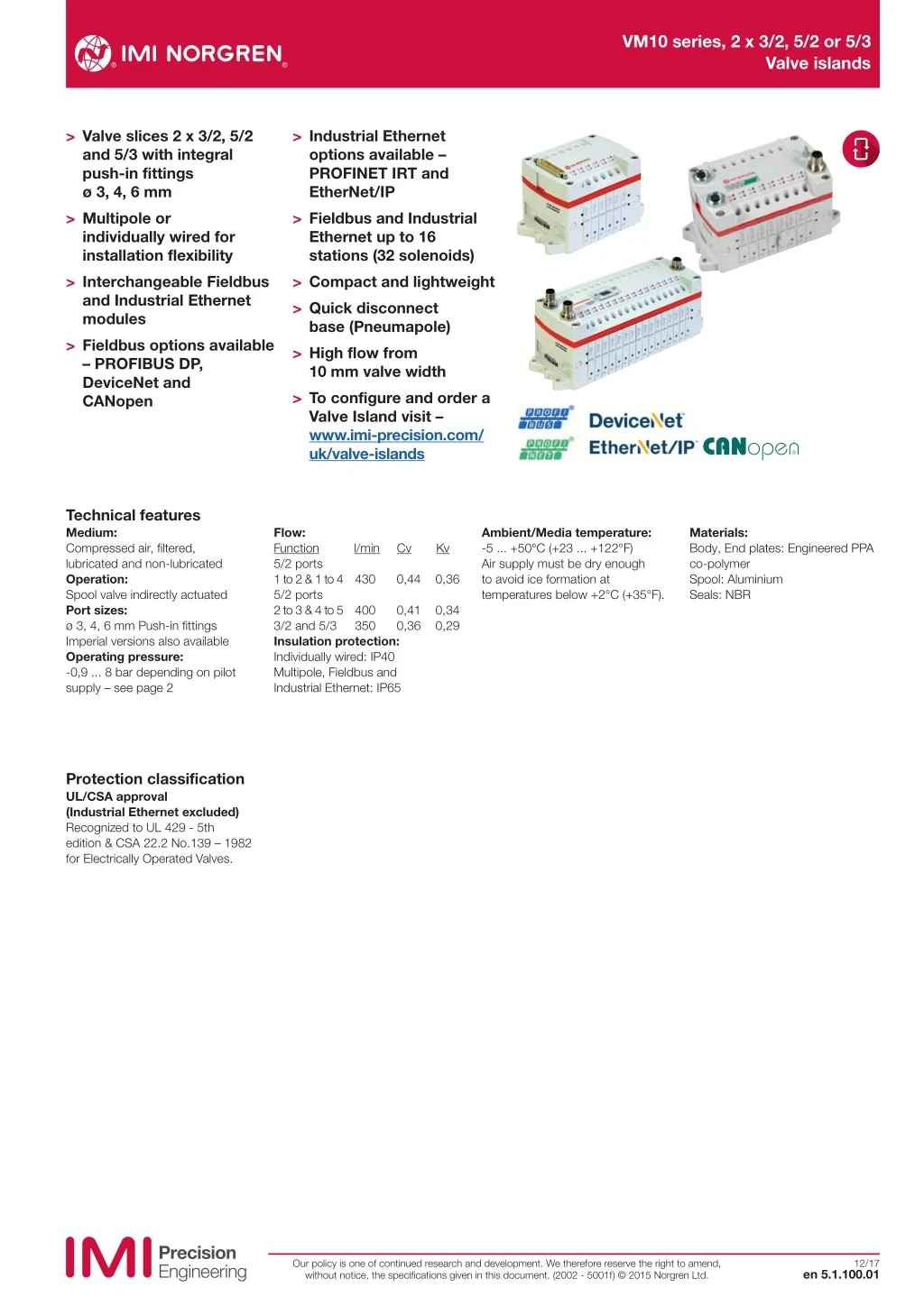
VM10 series, 2 x 3/2, 5/2 or 5/3 Valve islands > Valve slices 2 x 3/2, 5/2 and 5/3 with integral push-in fittings ø 3, 4, 6 mm > Multipole or individually wired for installation flexibility > Interchangeable Fieldbus and Industrial Ethernet modules > Fieldbus options available – PROFIBUS DP, DeviceNet and CANopen > Industrial Ethernet options available – PROFINET IRT and EtherNet/IP > Fieldbus and Industrial Ethernet up to 16 stations (32 solenoids) > Compact and lightweight > Quick disconnect base (Pneumapole) > High flow from 10 mm valve width > To configure and order a Valve Island visit – www.imi-precision.com/ uk/valve-islands Technical features Medium: Compressed air, filtered, lubricated and non-lubricated Operation: Spool valve indirectly actuated Port sizes: ø 3, 4, 6 mm Push-in fittings Imperial versions also available Operating pressure: -0,9 ... 8 bar depending on pilot supply – see page 2 Flow: Function 5/2 ports 1 to 2 & 1 to 4 430 5/2 ports 2 to 3 & 4 to 5 400 3/2 and 5/3 Insulation protection: Individually wired: IP40 Multipole, Fieldbus and Industrial Ethernet: IP65 Ambient/Media temperature: -5 ... +50°C (+23 ... +122°F) Air supply must be dry enough to avoid ice formation at temperatures below +2°C (+35°F). Materials: Body, End plates: Engineered PPA co-polymer Spool: Aluminium Seals: NBR l/min Cv Kv 0,44 0,36 0,41 0,36 0,34 0,29 350 Protection classification UL/CSA approval (Industrial Ethernet excluded) Recognized to UL 429 - 5th edition & CSA 22.2 No.139 – 1982 for Electrically Operated Valves. Our policy is one of continued research and development. We therefore reserve the right to amend, without notice, the specifications given in this document. (2002 - 5001f) © 2015 Norgren Ltd. 12/17 en 5.1.100.01
VM10 series, 2 x 3/2, 5/2 or 5/3 Valve islands Technical data 2 x 3/2 Double solenoid actuated valves Symbol Function Actuation Pilot supply Manual override Operating pressure (bar) (psi) Pilot pressure (bar) (psi) Weight (kg) Model 2 x 3/2 NC Solenoid/Spring Internal Turn & lock 3 ... 8 43 ... 116 — — 0,054 VM10*A11AB213B 410 2 14 10 12 2 x 3/2 NC Solenoid/Spring Internal Push only 3 ... 8 43 ... 116 — — 0,054 VM10*A11AB313B 84 82 5 1 3 2 x 3/2 NC Solenoid/Spring External Turn & lock -0,9 ... 8 -13 ... 116 3 ... 8 43 ... 116 0,054 VM10*A22AB213B 410 2 14 10 12 2 x 3/2 NC Solenoid/Spring External Push only -0,9 ... 8 -13 ... 116 3 ... 8 43 ... 116 0,054 VM10*A22AB313B 84 82 14/12 5 1 3 2 x 3/2 NO Solenoid/Spring Internal Turn & lock 3 ... 8 43 ... 116 — — 0,054 VM10*B11AB213B 414 2 10 12 10 2 x 3/2 NO Solenoid/Spring Internal Push only 3 ... 8 43 ... 116 — — 0,054 VM10*B11AB313B 84 82 3 5 1 2 x 3/2 NO Solenoid/Spring External Turn & lock -0,9 ... 8 -13 ... 116 3 ... 8 43 ... 116 0,054 VM10*B22AB213B 414 2 10 12 10 2 x 3/2 NO Solenoid/Spring External Push only -0,9 ... 8 -13 ... 116 3 ... 8 43 ... 116 0,054 VM10*B22AB313B 84 82 14/12 5 1 3 2 x 3/2 NO/NC Solenoid/Spring Internal Turn & lock 3 ... 8 43 ... 116 — — 0,054 VM10*C11AB213B 410 2 14 12 10 2 x 3/2 NO/NC Solenoid/Spring Internal Push only 3 ... 8 43 ... 116 — — 0,054 VM10*C11AB313B 84 82 3 5 1 2 x 3/2 NO/NC Solenoid/Spring External Turn & lock -0,9 ... 8 -13 ... 116 3 ... 8 43 ... 116 0,054 VM10*C22AB213B 410 2 14 12 10 2 x 3/2 NO/NC Solenoid/Spring External Push only -0,9 ... 8 -13 ... 116 3 ... 8 43 ... 116 0,054 VM10*C22AB313B 84 82 14/12 5 1 3 5/2 Single and double solenoid actuated valves 14 Symbol Function Actuation Pilot supply Manual override Operating pressure (bar) (psi) Pilot pressure (bar) (psi) Weight (kg) Model 5/2 5/2 Solenoid/Spring Solenoid/Spring Internal Internal Turn & lock Push only 3 ... 8 3 ... 8 43 ... 116 43 ... 116 — — — — 0,044 0,044 VM10*517AB213B VM10*517AB313B 2 4 14 12 5 3 1 5/2 5/2 Solenoid/Spring Solenoid/Spring External External Turn & lock Push only -0,9 ... 8 -0,9 ... 8 -13 ... 116 -13 ... 116 3 ... 8 3 ... 8 43 ... 116 43 ... 116 0,044 0,044 VM10*527AB213B VM10*527AB313B 14 2 4 12 2 4 14 12 14 5 3 1 5 3 1 2 5/2 5/2 Solenoid/Solenoid Solenoid/Solenoid Internal Internal Turn & lock Push only 2 ... 8 2 ... 8 29 ... 116 29 ... 116 — — — — 0,054 0,054 VM10*511AB213B VM10*511AB313B 4 4 14 12 14 12 5 3 5 1 1 3 5/2 Solenoid/Solenoid External Turn & lock -0,9 ... 8 -13 ... 116 2 ... 8 29 ... 116 0,054 VM10*522AB213B 2 4 2 4 14 12 5/2 Solenoid/Solenoid External Push only -0,9 ... 8 -13 ... 116 2 ... 8 29 ... 116 0,054 VM10*522AB313B 14 12 5 3 1 5/3 Double solenoid actuated valves 2 Symbol Function Actuation Pilot supply Manual override Operating pressure (bar) (psi) Pilot pressure (bar) (psi) Weight (kg) Model 5/3 APB 5/3 APB Solenoid/Solenoid Solenoid/Solenoid Internal Internal Turn & lock Push only 3 ... 8 3 ... 8 43 ... 116 43 ... 116 — — — — 0,055 0,055 VM10*611AB213B VM10*611AB313B 2 2 4 14 12 5 3 1 5/3 APB 5/3 APB Solenoid/Solenoid Solenoid/Solenoid External External Turn & lock Push only -0,9 ... 8 -0,9 ... 8 -13 ... 116 -13 ... 116 3 ... 8 3 ... 8 43 ... 116 43 ... 116 0,055 0,055 VM10*622AB213B VM10*622AB313B 2 4 14 14 12 5 1 3 * For selection of port sizes please see page 3 Note: For 5/3 COE please use 2 x 3/2 NC. For 5/3 COP please use 2 x 3/2 NO APB = All Ports Blocked COE = Centre Open Exhaust COP = Centre Open Pressure NC = Normally Closed NO = Normally Open 2 4 Electrical details Solenoids 24 V d.c. 0,6 W* Flywheel diode Yellow LED ± 10% 100% ED Voltage Surge suppression Indication * 12 V d.c. also available. Please consult our Technical Service. Voltage tolerance Rating Our policy is one of continued research and development. We therefore reserve the right to amend, without notice, the specifications given in this document. (2002 - 5001f) © 2015 Norgren Ltd. en 5.1.100.02 12/17
VM10 series, 2 x 3/2, 5/2 or 5/3 Valve islands Option selector - valve slices VM10˙˙˙˙AB˙13B Tube size 3 mm PIF 4 mm PIF 6 mm PIF No PIF (for use with Pneumapole) *1) Valve function 5/2 5/3 APB 2 x 3/2 NC and 5/3 COE 2 x 3/2 NO and 5/3 COP 2 x 3/2 NC and NO Substitute Manual override Turn to lock Push only Actuation/pilot supply Solenoid/solenoid internal pilot Solenoid/spring internal pilot *2) Solenoid/solenoid external pilot Solenoid/spring external pilot *2) Substitute 3 4 6 7 2 3 Substitute 11 17 22 27 Substitute 5 6 A B C To order a complete valve island please use the configurator at; www.imi-precision.com/uk/valve-islands Note: For 5/3 COE and COP use 2 x 3/2 APB = All Ports Blocked COE = Centre Open Exhaust COP = Centre Open Pressure NC = Normally Closed NO = Normally Open For valve island specification see page 16 and 17 *1) Requires Pneumapole sub-base *2) Can only be used with 5/2 valve Our policy is one of continued research and development. We therefore reserve the right to amend, without notice, the specifications given in this document. (2002 - 5001f) © 2015 Norgren Ltd. en 5.1.100.03 12/17
VM10 series, 2 x 3/2, 5/2 or 5/3 Valve islands Accessories Valve blanking station Pressure zone plate Pneumapole sub-base Page 6 Page 6 Page 13 & 14 VM106517AQ0300 VM106517AQ0301 (Port 1 blanked) VM106517AQ0302 (Ports 3 & 5 blanked) VM106517AQ0303 (Ports 1, 3 & 5 blanked) Details see page DIN Rail fixing kit DIN rail Label cover kit Labels V11900-C01, 8D V10009-C00 (1 m) V12016-K36 (4 Station) V12016-K37 (6 Station) V12016-K38 (8 Station) V12016-K39 (10 Station) V12016-K40 (12 Station) V12016-K41 (16 Station) V12033-L02 (write and seal label) V12034-L02 (paper label) Pressure switch for pilot ports 12 and 14 Silencer Plug Manual override kit Push only Rotate by hand, lockable Page 19 Page 19 Page 19 VM106517AQ0804 (4 mm) VM106517AQ0806 (6 mm) T45P0006 (6 mm) T45P0008 (8 mm) T45P0010 (10 mm) T45P0012 (12 mm) C00040600 (6 mm) C00040800 (8 mm) C00041000 (10 mm) C00041200 (12 mm) V11574-K30 V11574-K31 D Sub-connector 25 pin, IP65 D Sub-connector 44 pin, IP65 D Sub-connector 25 pin 90°, IP65 D Sub-connector 44 pin 90°, IP65 2 Pin connector IP40 Page 17 Page 17 Page 18 Page 18 V11569-E01 (1 m) V11569-E03 (3 m) V11569-E05 (5 m) V11570-E01 (1 m) V11570-E03 (3 m) V11570-E05 (5 m) V12086-E01 (1 m) V12086-E03 (3 m) V12086-E05 (5 m) V12088-E01 (1 m) V12088-E03 (3 m) V12088-E05 (5 m) V11556-E10 (1 m) V11556-E03 (0,3 m) Our policy is one of continued research and development. We therefore reserve the right to amend, without notice, the specifications given in this document. (2002 - 5001f) © 2015 Norgren Ltd. en 5.1.100.04 12/17
VM10 series, 2 x 3/2, 5/2 or 5/3 Valve islands Fieldbus accessories Description Fielbus power connector DeviceNet (4 pin, female) CANopen (4 pin, female) PROFIBUS DP (4 pin, female) Connection M12 Cable length Wireable Protection class IP65 Short code* R1 Model V11588-E01 DeviceNet (5 pin, female) CANopen (5 pin, female) M12 Wireable IP65 R2 V11589-E01 PROFIBUS DP, reverse keyway (5 pin, female) M12 Wireable IP65 R3 V11590-E01 PROFIBUS DP, reverse keyway (5 pin male) M12 Wireable IP65 R4 V11591-E01 PROFIBUS DP connector (9 pin, male with terminating resistor) D-Sub Wireable IP40 R0 V11654-E01 PROFIBUS DP terminating resistor M12 - IP65 R6 V11592-E01 * Short code – used in the Online Configurator Our policy is one of continued research and development. We therefore reserve the right to amend, without notice, the specifications given in this document. (2002 - 5001f) © 2015 Norgren Ltd. en 5.1.100.05 12/17
VM10 series, 2 x 3/2, 5/2 or 5/3 Valve islands Dimensions Dimensions in mm Projection/First angle Single solenoid Double solenoid 5/3 APB, double solenoid 10,6 10,6 10,6 2 4 6 6 2 2 6 6 6 6 6 6 6 6 4 6 4 6 78,5 5 78,5 78,5 11,5 11,5 11,5 2 1 2 1 2 1 53 53 53 32 32 15 32 15 15 5/2 Single and double solenoid actuated valves 5/3 Double solenoid actuated valves 2 x 3/2 Double solenoid actuated valves Model Short code * Weight (kg) Model Short code * Weight (kg) Model Short code * Weight (kg) NG*T 0,044 NA*T 0,054 NL*T 0,055 VM10*517AB213B VM10*A11AB213B VM10*611AB213B NG*U 0,044 NA*U 0,054 NL*U 0,055 VM10*A11AB313B VM10*517AB313B VM10*611AB313B NH*T 0,044 ND*T 0,054 NLZT 0,055 VM10*527AB213B VM10*A22AB213B VM107611AB213B NH*U 0,044 ND*U 0,054 NLZU 0,055 VM10*527AB313B VM10*A22AB313B VM107611AB313B NJ*T 0,054 NB*T 0,054 NM*T 0,055 VM10*511AB213B VM10*B11AB213B VM10*622AB213B NJ*U 0,054 NB*U 0,054 NM*U 0,055 VM10*511AB313B VM10*B11AB313B VM10*622AB313B NK*T 0,054 NE*T 0,054 NMZT 0,055 VM10*522AB213B VM10*B22AB213B VM107622AB213B NK*U 0,054 NE*U 0,054 NMZU 0,055 VM10*B22AB313B VM107622AB313B VM10*522AB313B NC*T 0,054 VM10*C11AB213B NC*U 0,054 VM10*C11AB313B NF*T 0,054 VM10*C22AB213B NF*U 0,054 VM10*C22AB313B Blanking and pressure zone plates 10,6 78,5 56 Blanking and pressure zone plates Short code * Weight (kg) VM106517AQ0300 VM106517AQ0301 VM106517AQ0302 Pressure zone plate (ports 3 & 5 blanked) VM106517AQ0303 Pressure zone plate (ports 1, 3 & 5 blanked) Blanking plate ports open Pressure zone plate (port 1 blanked) B000 B100 B300 B500 0,028 0,028 0,028 0,028 * Short code - used in Online Configurator Note: When using a pressure zone plate blanking port 1, it is not possible to use all internal pilot valves on both sides of the zone plate, at least one external pilot valve needs to be used. For further information please contact our technical service. Our policy is one of continued research and development. We therefore reserve the right to amend, without notice, the specifications given in this document. (2002 - 5001f) © 2015 Norgren Ltd. en 5.1.100.06 12/17
VM10 series, 2 x 3/2, 5/2 or 5/3 Valve islands Valve Island dimensions and port connections Dimensions in mm Projection/First angle 76 + (10,6 x N) 19 + (10,6 x N) 21,5 18,5 3 53 6 11 5 1 15 4 10,6 1 12/14 12/14 4,8 M4 M4 2 2 2 2 2 2 2 2 3 3 2 78,5 58,5 M4 48 30 15 1 Ports 12/14 2 Ports 1, 3 & 5 3 Ports 82/84 N = number of stations Detailed CAD drawings available at: www.imi-precision.com/uk/valve-islands 5 1 5 1 4 4 4 4 4 4 4 4 3 M4 M4 82/84 82/84 Description Ports 1 ,3 & 5 Tube outside ø Ports 12/14 & 82/84 Tube outside ø Ports 2 & 4 Tube outside ø Short code *1) Weight (kg) Model End plate kit - feed both ends End plate kit - feed both ends End plate kit - feed left, right blocked End plate kit - feed left, right blocked End plate kit - feed right, left blocked End plate kit - feed right, left blocked End plate kit - feed both ends - Pneumapole End plate kit - feed left, right blocked - Pneumapole End plate kit - feed right, left blocked - Pneumapole 10 8 10 8 10 8 no PIF *2) no PIF *2) no PIF *2) 6 4 6 4 6 4 no PIF *2) no PIF *2) no PIF *2) 6 4 6 4 6 4 no PIF *2) no PIF *2) no PIF *2) F100 F800 L100 L800 R100 R800 FPZ0 RPZ0 LPZ0 0,170 0,170 0,170 0,170 0,170 0,170 0,170 0,170 0,170 VM106517AQ010Y VM106517AQ0108 VM106517AQ011Y VM106517AQ0118 VM106517AQ012Y VM106517AQ0128 VM106517AQ0131 VM106517AQ0132 VM106517AQ0133 Available valve port sizes – ø 3 mm, 4 mm and 6 mm *1) Short code – used in the Online Configurator *2) No push in fitting for use with pneumapole sub-base Panel cut-out detail 4 For mounting island from outside of panel using M4 threads in valve island end plates 5 For using through-mounting holes in valve island end plates 4 4,5 75 48 5 5 52 + (N x 10,6) 63 + (N x 10,6) Our policy is one of continued research and development. We therefore reserve the right to amend, without notice, the specifications given in this document. (2002 - 5001f) © 2015 Norgren Ltd. en 5.1.100.07 12/17
VM10 series, 2 x 3/2, 5/2 or 5/3 Valve islands Top cover connections - Individually wired and Multipole Individually wired IP40 (no top cover) Dimensions in mm Projection/First angle 2 1 78,5 1 2 Pin connector 2 Manual override N = number of stations 38 53 11,5 10,6 76 + (N x 10,6) 56,5 Individually wired 2 Pin connector No. of stations 2 ... 20 Max. no. of solenoids 40 Weight (kg)* 0,170 * kg + valves weight Multipole IP65 4 80 3 5 78,5 3 25 Pin connector for 4, 6, 8, 10 & 12 station 44 Pin connector for 12 & 16 station 4 Manual override, actuate with srew driver N = number of stations 83 43,3 10,6 86,5 76 + (N x 10,6) Multipole 25 Pin connector 25 Pin connector 25 Pin connector 25 Pin connector 25 Pin connector 44 Pin connector 44 Pin connector No. of stations 4 6 8 10 12 12 16 -ve common Model VM106517AQ0404 VM106517AQ0406 VM106517AQ0408 VM106517AQ0410 VM106517AQ0412 VM106517AQ0512 VM106517AQ0516 Short code * 2N04 2N06 2N08 2N10 2N12 4N12 4N16 +ve common Model VM106517RQ0404 Short code * 2P04 Max. no. of solenoids 8 12 16 20 24 24 32 Weight (kg) 0,116 0,122 0,128 0,134 0,140 0,144 0,160 VM106517RQ0408 2P08 VM106517RQ0412 2P12 VM106517RQ0516 4P16 * Short code – used in the Online Configurator Our policy is one of continued research and development. We therefore reserve the right to amend, without notice, the specifications given in this document. (2002 - 5001f) © 2015 Norgren Ltd. en 5.1.100.08 12/17
VM10 series, 2 x 3/2, 5/2 or 5/3 Valve islands Top cover connections - Fieldbus and Industrial Ethernet PROFIBUS DP (M12 connector IP65) 1 4 5 80 5 Dimensions in mm Projection/First angle 78,5 34 1 M12 power connector 2 M12 protocol connector (male) 3 M12 protocol connector (female) 4 Rotary address switch 5 Manual override, actuate with screw driver N = number of stations 11 2 3 99,5 10,6 43,3 102,5 76 + (N x 10,6) Standard fieldbus No. of stations Max. no. of solenoids Short code * Weight (kg) Model PROFIBUS DP PROFIBUS DP PROFIBUS DP PROFIBUS DP 08 10 12 16 16 20 24 32 PS08 PS10 PS12 PS16 0,138 0,144 0,150 0,170 VM10DPFNB00082 VM10DPFNB00102 VM10DPFNB00122 VM10DPFNB00162 * Short code – used in the Online Configurator Connector details Power connection: M12 4-pin A-coded Bus connectors: M12 5-pin B coded Male Bus in Female Bus out Pin no. Function Male Pin no. Function Tolerance Max. current 1 2 3 4 5 5 VI Opto isolator A-line (green) 0 VI Opto isolated B-line (red) Shield 1 24 VB Logic circuit supply ±30% 300 mA 2 24 VA Valves ±10% 1,5 A 3 0 V – 1,53 A 4 Earth – – Our policy is one of continued research and development. We therefore reserve the right to amend, without notice, the specifications given in this document. (2002 - 5001f) © 2015 Norgren Ltd. en 5.1.100.09 12/17
VM10 series, 2 x 3/2, 5/2 or 5/3 Valve islands PROFINET IRT (M12 connector IP65) Dimensions for 8 and 10 stations Dimensions in mm Projection/First angle 92 5 85,5 3 80 4 5 78,5 36 20,7 14 12 14 12 14 12 14 12 14 12 14 12 14 12 14 12 10 10 1 M12 power connector (male) 2 M12 protocol connector (female) 3 M12 protocol connector (female) 4 Functional earth 5 Manual override, actuate with screw driver N = number of stations 96,5 10,6 43,3 76 + (N x 10,6) 99,5 2 1 Dimensions for 12 and 16 stations 99,2 92,7 87,2 5 78,5 36 20,7 14 12 14 12 14 12 14 12 14 12 14 12 14 12 14 12 14 12 14 12 14 12 14 12 10 10 103,7 43,3 10,6 76 + (N x 10,6) 106,7 Industrial Ethernet protocol No. of stations Max. no. of solenoids Short code * Weight (kg) Model PROFINET IRT PROFINET IRT PROFINET IRT PROFINET IRT 8 10 12 16 16 20 24 32 PN08 PN10 PN12 PN16 0,3 0,32 0,35 0,37 VM10PNIEB00080 VM10PNIEB00100 VM10PNIEB00120 VM10PNIEB00160 * Short code – used in the Online Configurator Connector details Power connector: M12 5-pin A-coded Bus connectors: M12 4-pin D-coded Male Pin no. 1 2 3 4 5 Function L1 (VB+) 24V electronics power supply N2 (VA-) 0V valves power supply N1 (VB-) 0V electronics power supply L2 (VA+) 24V valves power supply FE (functional earth) Female In Pin no. 1 2 3 4 housing Function Transmission Data + (TD+) Receive Data + (RD+) Transmission Data - (TD -) Receive Data - (RD -) (FE) functional earth Our policy is one of continued research and development. We therefore reserve the right to amend, without notice, the specifications given in this document. (2002 - 5001f) © 2015 Norgren Ltd. en 5.1.100.10 12/17
VM10 series, 2 x 3/2, 5/2 or 5/3 Valve islands DeviceNet and CANopen (M12 connector IP65) 1 4 5 80 Dimensions in mm Projection/First angle 5 78,5 34 11 1 M12 power connector 2 M12 protocol connector 4 Rotary address switch 5 Manual override, actuate with srew driver N = number of stations 2 99,5 10,6 43,3 102,5 76 + (N x 10,6) Standard fieldbus No. of stations Max. no. of solenoids Short code * Weight (kg) Model DeviceNet DeviceNet DeviceNet DeviceNet CANopen CANopen CANopen CANopen 08 10 12 16 08 10 12 16 16 20 24 32 16 20 24 32 DR08 DR10 DR12 DR16 CR08 CR10 CR12 CR16 0,138 0,144 0,150 0,170 0,138 0,144 0,150 0,170 VM10DNFNB00082 VM10DNFNB00102 VM10DNFNB00122 VM10DNFNB00162 VM10CAFNB00082 VM10CAFNB00102 VM10CAFNB00122 VM10CAFNB00162 * Short code – used in the Online Configurator Connector details Power connection: M12 4-pin A-coded Bus connector: M12 5-pin B-coded Male Pin no. 1 Function 24 VB Logic circuit supply Tolerance ±30% Max. current 300 mA Male Pin no. 1 2 3 4 5 Function Drain V+ V- CAN_H CAN_L2 2 24 VA Valves ±10% 1,5 A 3 0 V – 1,53 A 4 Earth – – Our policy is one of continued research and development. We therefore reserve the right to amend, without notice, the specifications given in this document. (2002 - 5001f) © 2015 Norgren Ltd. en 5.1.100.11 12/17
VM10 series, 2 x 3/2, 5/2 or 5/3 Valve islands EtherNet/IP (M12 connector IP65) Dimensions in mm Projection/First angle Dimensions for 8 and 10 stations 92 5 85,5 3 80 4 5 78,5 36 20,7 14 12 14 12 14 12 14 12 14 12 14 12 14 12 14 12 10 10 96,5 10,6 43,3 1 M12 power connector (male) 2 M12 protocol connector (female) 3 M12 protocol connector (female) 4 Functional earth 5 Manual override, actuate with screw driver N = number of stations 76 + (N x 10,6) 99,5 2 1 Dimensions for 12 and 16 stations 99,2 92,7 87,2 5 78,5 36 20,7 14 12 14 12 14 12 14 12 14 12 14 12 14 12 14 12 14 12 14 12 14 12 14 12 10 10 103,7 43,3 10,6 76 + (N x 10,6) 106,7 Industrial Ethernet protocol No. of stations Max. no. of solenoids Short code * Weight (kg) Model EtherNet/IP EtherNet/IP EtherNet/IP EtherNet/IP 8 10 12 16 16 20 24 32 EP08 EP10 EP12 EP16 0,3 0,32 0,35 0,37 VM10EPIEB00080 VM10EPIEB00100 VM10EPIEB00120 VM10EPIEB00160 * Short code – used in the Online Configurator Connector details Power connector: M12 5-pin A-coded Bus connectors: M12 4-pin D-coded Male Pin no. 1 2 3 4 5 Function L1 (VB+) 24V electronics power supply N2 (VA-) 0V valves power supply N1 (VB-) 0V electronics power supply L2 (VA+) 24V valves power supply FE (functional earth) Female Pin no. 1 2 3 4 housing Function Transmission Data + (TD+) Receive Data + (RD+) Transmission Data - (TD -) Receive Data - (RD -) (FE) functional earth Our policy is one of continued research and development. We therefore reserve the right to amend, without notice, the specifications given in this document. (2002 - 5001f) © 2015 Norgren Ltd. en 5.1.100.12 12/17
VM10 series, 2 x 3/2, 5/2 or 5/3 Valve islands Pneumapole sub-base – bottom ported Dimensions in mm Projection/First angle 4 3 18,5 A 18,5 15,3 15,3 30 6 10,6 6 22,5 1 < 4 4 4 M4 14,8 14,8 58,5 71,5 92,5 71,5 58,5 79 30 15 30 106 21 3 M6 M4 14,5 10 M4 5 8 15,5 10,5 2 M4 86,5 48 48 1 x 8 mm deep 2 x 12 mm deep 3 Side mounting option. Centre clamp to be removed if utilised. 4x 11 mm deep (12 & 16 station version only) 4,5 2,5 22 22 B Description Ports 1, 3 & 5 Ports 12/14 & 82/84 Ports 2 & 4 Short code * Model No. of stations A B 4 station Pneumapole 6 station Pneumapole 8 station Pneumapole 10 station Pneumapole 12 station Pneumapole 16 station Pneumapole 10 mm 10 mm 10 mm 10 mm 10 mm 10 mm 6 mm 6 mm 6 mm 6 mm 6 mm 6 mm 6 mm 6 mm 6 mm 6 mm 6 mm 6 mm 6B04 6B06 6B08 6B10 6B12 6B16 VM106517AQ6604 VM106517AQ6606 VM106517AQ6608 VM106517AQ6610 VM106517AQ6612 VM106517AQ6616 4 6 8 10 12 16 61,5 82,5 104 125 146,5 189 123,5 144,5 165,5 186,5 207,5 249,5 * Short code – used in the Online Configurator Note: Ports 82/84 (solenoid pilot exhausts) should not be plugged. A filter or silencer can be fitted or the air can be piped away with tubing. Panel cut-out detail 15 15 7,5 No. of stations 4 6 8 10 12 16 C 111 132 153 174 195 237 D 92 113,5 134,5 155,5 177 219,5 71,5 75,5 5 7,5 D C Our policy is one of continued research and development. We therefore reserve the right to amend, without notice, the specifications given in this document. (2002 - 5001f) © 2015 Norgren Ltd. en 5.1.100.13 12/17
VM10 series, 2 x 3/2, 5/2 or 5/3 Valve islands Pneumapole sub-base – side ported Dimensions in mm Projection/First angle A 15,5 14,8 10,6 15,5 M5 3 9,5 16 22,5 20 13 32 22 A 47 22 11,5 12,5 12,5 6 6 8 8 4 ø 3 4 2 M4 93 83 63 63 30 30 48 15 30 5,5 A 12 30 3 4 7,5 21 22,5 22,5 18,5 18,5 4,5 4,5 5 55,5 86,5 4,5 1 x 8 mm deep 2 x 8 mm deep 3 x 10 mm deep 4x 11 mm deep (12 & 16 station version only) 5 x 4,5 mm deep 7,5 3 3 B Description Port 1 Ports 3 & 5 Ports 12/14 & 82/84 Ports 2 & 4 Short code * Model No. of stations A B 4 station Pneumapole 6 station Pneumapole 8 station Pneumapole 10 station Pneumapole 12 station Pneumapole 16 station pneumapole 10 mm 10 mm 10 mm 10 mm 10 mm 10 mm 8 mm 8 mm 8 mm 8 mm 8 mm 8 mm 6 mm 6 mm 6 mm 6 mm 6 mm 6 mm 6 mm 6 mm 6 mm 6 mm 6 mm 6 mm 6S04 6S06 6S08 6S10 6S12 6S16 VM106517AQ6S04 VM106517AQ6S06 VM106517AQ6S08 VM106517AQ6S10 VM106517AQ6S12 VM106517AQ6S16 4 6 8 10 12 16 61,5 82,5 104 125 146,5 189 123,5 144,5 165,5 186,5 207,5 249,5 * Short code – used in the Online Configurator Note: Ports 82/84 (solenoid pilot exhausts) should not be plugged. A filter or silencer can be fitted or the air can be piped away with tubing. Panel cut-out detail No. of stations 4 6 8 10 12 16 C 80 101 122 143 164 206 D 92,5 113,5 135 156 177,5 220 25 6 17 27 6 C 6Additional cut-out required when rear mounting 12 & 16 station versions D Our policy is one of continued research and development. We therefore reserve the right to amend, without notice, the specifications given in this document. (2002 - 5001f) © 2015 Norgren Ltd. en 5.1.100.14 12/17
VM10 series, 2 x 3/2, 5/2 or 5/3 Valve islands Multi-pressure options Single pressure Two pressure Dimensions in mm Projection/First angle Pressure 1 Pressure 2 Pressure 1 Blanking slice gallery 1 VM106517AQ0301 Three pressure Four pressure Pressure 2 Pressure 1 Pressure 3 Port 3 Port 3a Port 3b Pressure 1 Pressure 3 Pressure 2 Pressure 4 Port 5 Port 5a Port 5b Pressure zone plate ports 1, 3 & 5 blanked VM106517AQ0303 Pressure zone plate ports 3 & 5 blanked VM106517AQ0302 Note: When using a pressure zone plate blanking port 1, it is not possible to use all internal pilot valves on both sides of the zone plate, at least one external pilot valve needs to be used. For further information please contact our technical service. Three and four pressure zone islands are achieved by using externally piloted 2 x 3/2 valves and reverse porting via ports 3 and 5. By reverse porting the valve’s function s also reversed so that a NC becomes NO and NO becomes NC. Our policy is one of continued research and development. We therefore reserve the right to amend, without notice, the specifications given in this document. (2002 - 5001f) © 2015 Norgren Ltd. en 5.1.100.15 12/17
VM10 series, 2 x 3/2, 5/2 or 5/3 Valve islands D sub-connector 25 pin (IP65) D Sub-connector 44 pin (IP65) Dimensions in mm Projection/First angle A A 100 100 30 44 15 25 13 5 5 14 1 31 1 16 A 1 m 3 m 5 m Model V11569-E01 V11569-E03 V11569-E05 A 1 m 3 m 5 m Model V11570-E01 V11570-E03 V11570-E05 Pin no. 1 2 3 4 5 6 7 8 9 10 11 12 13 14 15 16 17 18 19 20 21 22 23 24 25 Wire colour White Brown Green Yellow Grey Pink Blue Red Black Violet Grey/Pink Red/Blue White/Green Brown/Green White/Yellow Yellow/Brown White/Grey Grey/Brown White/Pink Pink/Brown White/Blue Brown/Blue White/Red Brown/Red White/Black Socket Solenoid 1–a Solenoid 2–a Solenoid 3–a Solenoid 4–a Solenoid 5–a Solenoid 6–a Solenoid 7–a Solenoid 8–a Solenoid 9–a Solenoid 10–a Solenoid 11–a Solenoid 12–a Common-Ve Solenoid 1–b Solenoid 2–b Solenoid 3–b Solenoid 4–b Solenoid 5–b Solenoid 6–b Solenoid 7–b Solenoid 8–b Solenoid 9–b Solenoid 10–b Solenoid 11–b Solenoid 12–b Pilot 14 14 14 14 14 14 14 14 14 14 14 14 Station 1 2 3 4 5 6 7 8 9 10 11 12 — 1 2 3 4 5 6 7 8 9 10 11 12 Pin no. 1 2 3 4 5 6 7 8 9 10 11 12 13 14 15 16 17 18 19 20 21 22 23 24 25 26 27 28 29 30 31 32 33 34 35 36 37 38 39 40 41 42 43 44 Wire colour White Brown Green Yellow Grey Pink Blue Red Black Violet Grey/Pink Red/Blue White/Green Brown/Green White/Yellow Yellow/Brown White/Grey Grey/Brown White/Pink Pink/Brown White/Blue Brown/Blue White/Red Brown/Red White/Black Brown/Black Grey/Green Yellow/Grey Pink/Green Yellow/Pink Green/Blue Yellow/Blue — — — — — — — — — — — Red/Black Yellow/ Black Socket Solenoid 1–a Solenoid 2–a Solenoid 3–a Solenoid 4–a Solenoid 5–a Solenoid 6–a Solenoid 7–a Solenoid 8–a Solenoid 9–a Solenoid 10–a Solenoid 11–a Solenoid 12–a Solenoid 13–a Solenoid 14–a Solenoid 15–a Solenoid 1–b Solenoid 2–b Solenoid 3–b Solenoid 4–b Solenoid 5–b Solenoid 6–b Solenoid 7–b Solenoid 8–b Solenoid 9–b Solenoid 10–b Solenoid 11–b Solenoid 12–b Solenoid 13–b Solenoid 14–b Solenoid 15–b Solenoid 16–a Solenoid 16–b Not used Not used Not used Not used Not used Not used Not used Not used Not used Not used Not used Common-Ve Pilot 14 14 14 14 14 14 14 14 14 14 14 14 14 14 14 12 12 12 12 12 12 12 12 12 12 12 12 12 12 12 14 12 — — — — — — — — — — — — Station 1 2 3 4 5 6 7 8 9 10 11 12 13 14 15 1 2 3 4 5 6 7 8 9 10 11 12 13 14 15 16 16 — — — — — — — — — — — — 12 12 12 12 12 12 12 12 12 12 12 12 Note: Conforms to IEC60757 Our policy is one of continued research and development. We therefore reserve the right to amend, without notice, the specifications given in this document. (2002 - 5001f) © 2015 Norgren Ltd. en 5.1.100.16 12/17
VM10 series, 2 x 3/2, 5/2 or 5/3 Valve islands D Sub-connector 25 pin 90° (IP65) D Sub-connector 44 pin 90° (IP65) Dimensions in mm Projection/First angle A A A A 100 100 16 31 1 25 13 5 5 44 15 14 1 30 A A A 1 m 3 m 5 m Model V12086-E01 V12086-E03 V12086-E05 A 1 m 3 m 5 m Model V12088-E01 V12088-E03 V12088-E05 Pin no. 1 2 3 4 5 6 7 8 9 10 11 12 13 14 15 16 17 18 19 20 21 22 23 24 25 Wire colour White Brown Green Yellow Grey Pink Blue Red Black Violet Grey/Pink Red/Blue White/Green Brown/Green White/Yellow Yellow/Brown White/Grey Grey/Brown White/Pink Pink/Brown White/Blue Brown/Blue White/Red Brown/Red White/Black Socket Solenoid 1–a Solenoid 2–a Solenoid 3–a Solenoid 4–a Solenoid 5–a Solenoid 6–a Solenoid 7–a Solenoid 8–a Solenoid 9–a Solenoid 10–a Solenoid 11–a Solenoid 12–a Common-Ve Solenoid 1–b Solenoid 2–b Solenoid 3–b Solenoid 4–b Solenoid 5–b Solenoid 6–b Solenoid 7–b Solenoid 8–b Solenoid 9–b Solenoid 10–b Solenoid 11–b Solenoid 12–b Pilot 14 14 14 14 14 14 14 14 14 14 14 14 Station 1 2 3 4 5 6 7 8 9 10 11 12 – 1 2 3 4 5 6 7 8 9 10 11 12 Pin no. 1 2 3 4 5 6 7 8 9 10 11 12 13 14 15 16 17 18 19 20 21 22 23 24 25 26 27 28 29 30 31 32 33 34 35 36 37 38 39 40 41 42 43 44 Wire colour White Brown Green Yellow Grey Pink Blue Red Black Violet Grey/Pink Red/Blue White/Green Brown/Green White/Yellow Yellow/Brown White/Grey Grey/Brown White/Pink Pink/Brown White/Blue Brown/Blue White/Red Brown/Red White/Black Brown/Black Grey/Green Yellow/Grey Pink/Green Yellow/Pink Green/Blue Yellow/Blue — — — — — — — — — — — Red/Black Yellow/ Black Socket Solenoid 1–a Solenoid 2–a Solenoid 3–a Solenoid 4–a Solenoid 5–a Solenoid 6–a Solenoid 7–a Solenoid 8–a Solenoid 9–a Solenoid 10–a Solenoid 11–a Solenoid 12–a Solenoid 13–a Solenoid 14–a Solenoid 15–a Solenoid 1–b Solenoid 2–b Solenoid 3–b Solenoid 4–b Solenoid 5–b Solenoid 6–b Solenoid 7–b Solenoid 8–b Solenoid 9–b Solenoid 10–b Solenoid 11–b Solenoid 12–b Solenoid 13–b Solenoid 14–b Solenoid 15–b Solenoid 16–a Solenoid 16–b Not used Not used Not used Not used Not used Not used Not used Not used Not used Not used Not used Common -Ve Pilot 14 14 14 14 14 14 14 14 14 14 14 14 14 14 14 12 12 12 12 12 12 12 12 12 12 12 12 12 12 12 14 12 — — — — — — — — — — — — Station 1 2 3 4 5 6 7 8 9 10 11 12 13 14 15 1 2 3 4 5 6 7 8 9 10 11 12 13 14 15 16 16 — — — — — — — — — — — — 12 12 12 12 12 12 12 12 12 12 12 12 Note: Conforms to IEC60757 Our policy is one of continued research and development. We therefore reserve the right to amend, without notice, the specifications given in this document. (2002 - 5001f) © 2015 Norgren Ltd. en 5.1.100.17 12/17
VM10 series, 2 x 3/2, 5/2 or 5/3 Valve islands Pressure switch for pilot ports 12 & 14 Dimensions in mm Projection/First angle Voltage Pressure range Switching point rising pressure Switch point falling pressure AMP E-terminals Degee of protection Adjustment 24 V d.c. 0 ... 10 bar 3 ... 5 bar 2,5 ... 3,7 bar 2,8 x 0,8 IP00 None 31,5 17 A Symbol A Short code Weight (kg) Model 4 6 7A 7B 0,004 0,004 VM106517AQ0804 VM106517AQ0806 3 1 Silencer Plug C0004 øK øA ø A 1 ø A F F E C C ø A 4 6 8 10 ø A1 4 6 8 10 C 30 34 38 42 F 17,5 18,5 21 24 Model C00040400 C00040600 C00040800 C00041000 ø A C E F ø K Model 4 6 8 10 32 45 43,5 57,5 16 24,5 22 31 14 17 19 23 6,5 12,5 13,5 15,5 T45P0004 T45P0006 T45P0008 T45P0010 Our policy is one of continued research and development. We therefore reserve the right to amend, without notice, the specifications given in this document. (2002 - 5001f) © 2015 Norgren Ltd. en 5.1.100.18 12/17
VM10 series, 2 x 3/2, 5/2 or 5/3 Valve islands Part numbering for complete valve islands VM10˙˙˙˙00-˙˙˙˙˙ To be defined by online Valve Island configurator based on valve slice selection Number of stations *1) 2 stations 3 stations 4 stations 5 stations 6 stations 7 stations 8 stations 9 stations 10 stations 11 stations 12 stations 13 stations 14 stations 15 stations 16 stations 17 stations 18 stations 19 stations 20 stations Electrical connection Individually Wired Multipole 25 pin Multipole 44 pin PROFIBUS DP PROFINET IRT DeviceNet EtherNet/IP CANopen Substitute 2 3 4 5 6 7 8 9 10 11 12 13 14 15 16 17 18 19 20 Substitute IW M2 M4 PB PN DN EP CO *1) Individually wired; 2 to 20 stations Multipole; 4, 6, 8, 10, 12 and 16 stations Fieldbus and Industrial Ethernet; 8, 10, 12 and 16 stations Our policy is one of continued research and development. We therefore reserve the right to amend, without notice, the specifications given in this document. (2002 - 5001f) © 2015 Norgren Ltd. en 5.1.100.19 12/17
VM10 series, 2 x 3/2, 5/2 or 5/3 Valve islands Descriptions and short codes for valve slices used in the Valve Island configurator Description 2 x 3/2 - 2 x NC - Internal feed valve 3 mm PIF 2 x 3/2 - 2 x NC - Internal feed valve 3 mm PIF 2 x 3/2 - 2 x NC - Internal feed valve 4 mm PIF 2 x 3/2 - 2 x NC - Internal feed valve 4 mm PIF 2 x 3/2 - 2 x NC - Internal feed valve 6 mm PIF 2 x 3/2 - 2 x NC - Internal feed valve 6 mm PIF 2 x 3/2 - 2 x NC - Internal feed valve Pneumapole 2 x 3/2 - 2 x NC - Internal feed valve Pneumapole 2 x 3/2 - 2 x NC - External feed valve 3 mm PIF 2 x 3/2 - 2 x NC - External feed valve 3 mm PIF 2 x 3/2 - 2 x NC - External feed valve 4 mm PIF 2 x 3/2 - 2 x NC - External feed valve 4 mm PIF 2 x 3/2 - 2 x NC - External feed valve 6 mm PIF 2 x 3/2 - 2 x NC - External feed valve 6 mm PIF 2 x 3/2 - 2 x NC - External feed valve Pneumapole 2 x 3/2 - 2 x NC - External feed valve Pneumapole Manual override Turn & lock Push only Turn & lock Push only Turn & lock Push only Turn & lock Push only Turn & lock Push only Turn & lock Push only Turn & lock Push only Turn & lock Push only Short code NA3T NA3U NA4T NA4U NA6T NA6U NAZT NAZU ND3T ND3U ND4T ND4U ND6T ND6U NDZT NDZU Model VM103A11AB213B VM103A11AB313B VM104A11AB213B VM104A11AB313B VM106A11AB213B VM106A11AB313B VM107A11AB213B VM107A11AB313B VM103A22AB213B VM103A22AB313B VM104A22AB213B VM104A22AB313B VM106A22AB213B VM106A22AB313B VM107A22AB213B VM107A22AB313B 2 x 3/2 - 2 x NO - Internal feed valve 3 mm PIF 2 x 3/2 - 2 x NO - Internal feed valve 3 mm PIF 2 x 3/2 - 2 x NO - Internal feed valve 4 mm PIF 2 x 3/2 - 2 x NO - Internal feed valve 4 mm PIF 2 x 3/2 - 2 x NO - Internal feed valve 6 mm PIF 2 x 3/2 - 2 x NO - Internal feed valve 6 mm PIF 2 x 3/2 - 2 x NO - Internal feed valve Pneumapole 2 x 3/2 - 2 x NO - Internal feed valve Pneumapole 2 x 3/2 - 2 x NO - External feed valve 3 mm PIF 2 x 3/2 - 2 x NO - External feed valve 3 mm PIF 2 x 3/2 - 2 x NO - External feed valve 4 mm PIF 2 x 3/2 - 2 x NO - External feed valve 4 mm PIF 2 x 3/2 - 2 x NO - External feed valve 6 mm PIF 2 x 3/2 - 2 x NO - External feed valve 6 mm PIF 2 x 3/2 - 2 x NO - External feed valve Pneumapole 2 x 3/2 - 2 x NO - External feed valve Pneumapole Turn & lock Push only Turn & lock Push only Turn & lock Push only Turn & lock Push only Turn & lock Push only Turn & lock Push only Turn & lock Push only Turn & lock Push only NB3T NB3U NB4T NB4U NB6T NB6U NBZT NBZU NE3T NE3U NE4T NE4U NE6T NE6U NEZT NEZU VM103B11AB213B VM103B11AB313B VM104B11AB213B VM104B11AB313B VM106B11AB213B VM106B11AB313B VM107B11AB213B VM107B11AB313B VM103B22AB213B VM103B22AB313B VM104B22AB213B VM104B22AB313B VM106B22AB213B VM106B22AB313B VM107B22AB213B VM107B22AB313B NC3T NC3U NC4T NC4U NC6T NC6U NCZT NCZU NF3T NF3U NF4T NF4U NF6T NF6U NFZT NFZU VM103C11AB213B VM103C11AB313B VM104C11AB213B VM104C11AB313B VM106C11AB213B VM106C11AB313B VM107C11AB213B VM107C11AB313B VM103C22AB213B VM103C22AB313B VM104C22AB213B VM104C22AB313B VM106C22AB213B VM106C22AB313B VM107C22AB213B VM107C22AB313B 2 x 3/2 - 1 x NC + 1 x NO - Internal feed valve 3 mm PIF 2 x 3/2 - 1 x NC + 1 x NO - Internal feed valve 3 mm PIF 2 x 3/2 - 1 x NC + 1 x NO - Internal feed valve 4 mm PIF 2 x 3/2 - 1 x NC + 1 x NO - Internal feed valve 4 mm PIF 2 x 3/2 - 1 x NC + 1 x NO - Internal feed valve 6 mm PIF 2 x 3/2 - 1 x NC + 1 x NO - Internal feed valve 6 mm PIF 2 x 3/2 - 1 x NC + 1 x NO - Internal feed valve Pneumapole 2 x 3/2 - 1 x NC + 1 x NO - Internal feed valve Pneumapole 2 x 3/2 - 1 x NC + 1 x NO - External feed valve 3 mm PIF 2 x 3/2 - 1 x NC + 1 x NO - External feed valve 3 mm PIF 2 x 3/2 - 1 x NC + 1 x NO - External feed valve 4 mm PIF 2 x 3/2 - 1 x NC + 1 x NO - External feed valve 4 mm PIF 2 x 3/2 - 1 x NC + 1 x NO - External feed valve 6 mm PIF 2 x 3/2 - 1 x NC + 1 x NO - External feed valve 6 mm PIF 2 x 3/2 - 1 x NC + 1 x NO - External feed valve Pneumapole 2 x 3/2 - 1 x NC + 1 x NO - External feed valve Pneumapole Turn & lock Push only Turn & lock Push only Turn & lock Push only Turn & lock Push only Turn & lock Push only Turn & lock Push only Turn & lock Push only Turn & lock Push only Our policy is one of continued research and development. We therefore reserve the right to amend, without notice, the specifications given in this document. (2002 - 5001f) © 2015 Norgren Ltd. en 5.1.100.20 12/17
VM10 series, 2 x 3/2, 5/2 or 5/3 Valve islands Description 5/2 Solenoid/spring - Internal feed valve 3 mm PIF 5/2 Solenoid/spring - Internal feed valve 3 mm PIF 5/2 Solenoid/spring - Internal feed valve 4 mm PIF 5/2 Solenoid/spring - Internal feed valve 4 mm PIF 5/2 Solenoid/spring - Internal feed valve 6 mm PIF 5/2 Solenoid/spring - Internal feed valve 6mm PIF 5/2 Solenoid/spring - Internal feed valve Pneumapole 5/2 Solenoid/spring - Internal feed valve Pneumapole 5/2 Solenoid/spring - External feed valve 3 mm PIF 5/2 Solenoid/spring - External feed valve 3 mm PIF 5/2 Solenoid/spring - External feed valve 4 mm PIF 5/2 Solenoid/spring - External feed valve 4 mm PIF 5/2 Solenoid/spring - External feed valve 6 mm PIF 5/2 Solenoid/spring - External feed valve 6 mm PIF 5/2 Solenoid/spring - External feed valve Pneumapole 5/2 Solenoid/spring - External feed valve Pneumapole Manual override Turn & lock Push only Turn & lock Push only Turn & lock Push only Turn & lock Push only Turn & lock Push only Turn & lock Push only Turn & lock Push only Turn & lock Push only Short code NG3T NG3U NG4T NG4U NG6T NG6U NGZT NGZU NH3T NH3U NH4T NH4U NH6T NH6U NHZT NHZU Model VM103517AB213B VM103517AB313B VM104517AB213B VM104517AB313B VM106517AB213B VM106517AB313B VM107517AB213B VM107517AB313B VM103527AB213B VM103527AB313B VM104527AB213B VM104527AB313B VM106527AB213B VM106527AB313B VM107527AB213B VM107527AB313B 5/2 Solenoid/solenoid - Internal feed valve 3 mm PIF 5/2 Solenoid/solenoid - Internal feed valve 3 mm PIF 5/2 Solenoid/solenoid - Internal feed valve 4 mm PIF 5/2 Solenoid/solenoid - Internal feed valve 4 mm PIF 5/2 Solenoid/solenoid - Internal feed valve 6 mm PIF 5/2 Solenoid/solenoid - Internal feed valve 6 mm PIF 5/2 Solenoid/solenoid - Internal feed valve Pneumapole 5/2 Solenoid/solenoid - Internal feed valve Pneumapole 5/2 Solenoid/solenoid - External feed valve 3 mm PIF 5/2 Solenoid/solenoid - External feed valve 3 mm PIF 5/2 Solenoid/solenoid - External feed valve 4 mm PIF 5/2 Solenoid/solenoid - External feed valve 4 mm PIF 5/2 Solenoid/solenoid - External feed valve 6 mm PIF 5/2 Solenoid/solenoid - External feed valve 6 mm PIF 5/2 Solenoid/solenoid - External feed valve Pneumapole 5/2 Solenoid/solenoid - External feed valve Pneumapole Turn & lock Push only Turn & lock Push only Turn & lock Push only Turn & lock Push only Turn & lock Push only Turn & lock Push only Turn & lock Push only Turn & lock Push only NJ3T NJ3U NJ4T NJ4U NJ6T NJ6U NJZT NJZU NK3T NK3U NK4T NK4U NK6T NK6U NKZT NKZU VM103511AB213B VM103511AB313B VM104511AB213B VM104511AB313B VM106511AB213B VM106511AB313B VM107511AB213B VM107511AB313B VM103522AB213B VM103522AB313B VM104522AB213B VM104522AB313B VM106522AB213B VM106522AB313B VM107522AB213B VM107522AB313B NL3T NL3U NL4T NL4U NL6T NL6U NLZT NLZU NM3T NM3U NM4T NM4U NM6T NM6U NMZT NMZU VM103611AB213B VM103611AB313B VM104611AB213B VM104611AB313B VM106611AB213B VM106611AB313B VM107611AB213B VM107611AB313B VM103622AB213B VM103622AB313B VM104622AB213B VM104622AB313B VM106622AB213B VM106622AB313B VM107622AB213B VM107622AB313B 5/3 APB Solenoid/solenoid - Internal feed valve 3 mm PIF 5/3 APB Solenoid/solenoid - Internal feed valve 3 mm PIF 5/3 APB Solenoid/solenoid - Internal feed valve 4 mm PIF 5/3 APB Solenoid/solenoid - Internal feed valve 4 mm PIF 5/3 APB Solenoid/solenoid - Internal feed valve 6 mm PIF 5/3 APB Solenoid/solenoid - Internal feed valve 6 mm PIF 5/3 APB Solenoid/solenoid - Internal feed valve Pneumapole 5/3 APB Solenoid/solenoid - Internal feed valve Pneumapole 5/3 APB Solenoid/solenoid - External feed valve 3 mm PIF 5/3 APB Solenoid/solenoid - External feed valve 3 mm PIF 5/3 APB Solenoid/solenoid - External feed valve 4 mm PIF 5/3 APB Solenoid/solenoid - External feed valve 4 mm PIF 5/3 APB Solenoid/solenoid - External feed valve 6 mm PIF 5/3 APB Solenoid/solenoid - External feed valve 6 mm PIF 5/3 APB Solenoid/solenoid - External feed valve Pneumapole 5/3 APB Solenoid/solenoid - External feed valve Pneumapole Turn & lock Push only Turn & lock Push only Turn & lock Push only Turn & lock Push only Turn & lock Push only Turn & lock Push only Turn & lock Push only Turn & lock Push only Our policy is one of continued research and development. We therefore reserve the right to amend, without notice, the specifications given in this document. (2002 - 5001f) © 2015 Norgren Ltd. en 5.1.100.21 12/17
VM10 series, 2 x 3/2, 5/2 or 5/3 Valve islands Descriptions and short codes for end plates used in the Valve Island configurator Description End plate kit - feed both ends End plate kit - feed both ends End plate kit - feed left, right blocked End plate kit - feed left, right blocked End plate kit - feed right, left blocked End plate kit - feed right, left blocked End plate kit - feed both ends - Pneumapole End plate kit - feed left, right blocked - Pneumapole End plate kit - feed right, left blocked - Pneumapole Manual override 10 mm 8 mm 10 mm 8 mm 10 mm 8 mm no PIF no PIF no PIF Short code F100 F800 L100 L800 R100 R800 FPZ0 RPZ0 LPZ0 Model VM106517AQ010Y VM106517AQ0108 VM106517AQ011Y VM106517AQ0118 VM106517AQ012Y VM106517AQ0128 VM106517AQ0131 VM106517AQ0132 VM106517AQ0133 Warning These products are intended for use in industrial compressed air systems only. Do not use these products where pressures and temperatures can exceed those listed under »Technical features/data«. Before using these products with fluids other than those specified, for non-industrial applications, life-support systems or other applications not within published specifications, consult IMI Precision Engineering, Norgren Ltd. Through misuse, age, or malfunction, components used in fluid power systems can fail in various modes. The system designer is warned to consider the failure modes of all component parts used in fluid power systems and to provide adequate safeguards to prevent personal injury or damage to equipment in the event of such failure. System designers must provide a warning to end users in the system instructional manual if protection against a failure mode cannot be adequately provided. System designers and end users are cautioned to review specific warnings found in instruction sheets packed and shipped with these products. Our policy is one of continued research and development. We therefore reserve the right to amend, without notice, the specifications given in this document. (2002 - 5001f) © 2015 Norgren Ltd. en 5.1.100.22 12/17