Download
1 / 2
20 likes | 26 Views
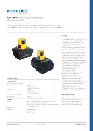
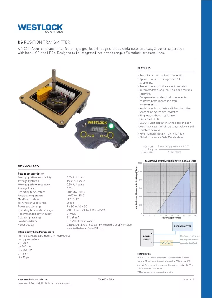
A 4-20 mA current transmitter featuring a gearless through shaft potentiameter and easy 2-button calibration with local LCD and LEDs. Designed to be integrated into a wide range of Westlock products lines.<br>For More Information visit on our website:- www.instronline.com<br>Our E-mail Address:-info@instronline.com <br>

E N D
DS POSITION TRANSMITTER A 4-20 mA current transmitter featuring a gearless through shaft potentiameter and easy 2-button calibration with local LCD and LEDs. Designed to be integrated into a wide range of Westlock products lines. FEATURES • Precision analog position transmitter. • Operates with any voltage from 9 to 30 volts DC. • Reverse polarity and transient protected. • Accommodates long cable runs and multiple receivers. • Encapsulation of electrical components improves performance in harsh environments. • Available with proximity switches, inductive sensors, or mechanical switches. • Simple push-button calibration • Bi-colored LEDs • LCD 3.5 Digit display showing position open • Automatic detection of rotation, clockwise and counterclockwise • Potentiometer Rotation up to 30°-200° • Global Intrinsically Safe Certification Power Supply Voltage - 9 V DC** Maximum Loop = 0.0021 Amps Resistance* TECHNICAL DATA Potentiometer Option Average position repetability Average hystersis Average position resolution Average linearity Operating temperature Ambient temperature Min/Max Rotation Transmitter update rate Power supply range Operating temperature range Recommended power supply Output signal range Load impedance Power supply 0.5% full scale 1% of full scale 0.5% full scale 0.5% -40°C to +80°C -40°C to +80°C 30° - 200° 20 ms 9 V DC to 30 V DC -40°F to +185°F [-40°C to +85°C] 24 V DC 4 to 20 mA 0 to 950 ohms at 24 V DC Output signal changes 0.018% when the supply voltage is varied between 5 and 33 V DC Intrinsically Safe Parameters Intrinsically safe parameters for loop output Entity parameters Ui = 30 V Ii = 100 mA Pi = 750 mW Ci = 5 nF Li = 10 μH Resistance in 4-20 mA Loop Including Cable, Barriers, and Analog-Input Card GRAPH NOTES *For a 24 V DC power supply and 700 Ohms in the 4-20 mA Loop, at 21 mA current draw that would be 700 Ohms x 0.021 A = 14.7 Volts across teh loop, which would leave 24V - 14.7 V = 9.3 V across the transmitter. **Minimum voltage to power transmitter www.westlockcontrols.com TD10053-ENr- Page 1 of 2 Copyright © Westlock Controls. All rights reserved.
DS POSITION TRANSMITTER TYPICAL WIRING DIAGRAM 4-20 mA TRANSMITTER 4-20 mA POSITION MEASURED OUTPUT BROWN BLUE RED WHITE BLACK SWITCH #1 UPPER RED WHITE BLACK SWITCH #2 LOWER GND 4-20 mA TRANSMITTER 4-20 mA POSITION MEASURED OUTPUT BROWN BLUE GND Translations Where translated the copy is taken from the original English document TD10053-EN as checked by the relevant notified certification body and therefore the original English document will prevail. No rights or liability can be derived from any translation. Crane Co., and its subsidiaries cannot accept responsibility for possible errors in catalogues, brochures, other prinited materials, and website information. Crane Co. reserves the right to alter its products without notice, including products already on order provided that such alterations can be made without changes being necessary in specifications already agreed. All trademarkts in this material are the property of Crane Co. ot its subsidiaties. The Crane and Crane brands logotype (WESTLOCK CONTROLS registered trademarks of Crane Co. All rights reserved. ® ) are WESTLOCK CONTROLS Head Office 280 N. Midland Avevnue, Ste. 258 Saddle Brook, NJ 07663 United States USA +1 201 794 7650 EUROPE +44 (0)1892 516277 ASIA +65 6266 4535 www.westlockcontrols.com TD10053-ENr- Page 2 of 2 Copyright © Westlock Controls. All rights reserved.