Download
1 / 26
270 likes | 756 Views
(C) R G Bingham 2005. All rights reserved.. Six pages on recognising some Seidel aberrations. (C) R G Bingham 2005. All rights reserved.. Why recognise Seidel aberrations?. Even in an imaging system that is very complex in design, total aberrations are not zero. Seidel terms will be included at some level, balancing higher-order aberrations. We can look for all such effects in order to see whether the design process was used, or is being used, to best advantage, as discussed elsewhere in this9443

E N D
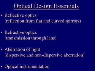
1. (C) R G Bingham 2005. All rights reserved. Optics and Optical Design
2. (C) R G Bingham 2005. All rights reserved.
3. (C) R G Bingham 2005. All rights reserved. Why recognise Seidel aberrations?
4. (C) R G Bingham 2005. All rights reserved. Why are spherical aberration and coma important in axisymmetrical systems?
5. (C) R G Bingham 2005. All rights reserved. Coma; its wavefront aberration plot (OPD). A reminder from session 2 with two forms of display
6. (C) R G Bingham 2005. All rights reserved. Spherical aberration and coma � rays
7. (C) R G Bingham 2005. All rights reserved. Ray FansSpherical aberration Coma
8. (C) R G Bingham 2005. All rights reserved. Spherical aberration and coma � spots
9. (C) R G Bingham 2005. All rights reserved. A warning regarding the use of aberration fans when the optical system is not axisymmetrical.
10. (C) R G Bingham 2005. All rights reserved. Image Quality
11. (C) R G Bingham 2005. All rights reserved. Image Quality
12. (C) R G Bingham 2005. All rights reserved. Afocal Systems, Image Quality and Telescopes
13. (C) R G Bingham 2005. All rights reserved. Obscuration and aberrations at the diffraction limit
14. (C) R G Bingham 2005. All rights reserved. Strehl Ratio - example
15. (C) R G Bingham 2005. All rights reserved. Strehl Ratio � calculations and convention
16. (C) R G Bingham 2005. All rights reserved. Strehl Ratio � warnings
17. (C) R G Bingham 2005. All rights reserved. Wavelength-compensation of image size
18. (C) R G Bingham 2005. All rights reserved. The correct focus should give the correct aberrations
19. (C) R G Bingham 2005. All rights reserved. Gaussian Beams
20. (C) R G Bingham 2005. All rights reserved. Modes in free space
21. (C) R G Bingham 2005. All rights reserved. Gaussian beam
22. (C) R G Bingham 2005. All rights reserved. Propagating Gaussian Beams in ZEMAX. The �Standard� or �Paraxial� formulae�. 1: Zero aberrations
23. (C) R G Bingham 2005. All rights reserved. The �Standard� or �Paraxial� formulae�. 2: Beware of M2.
24. (C) R G Bingham 2005. All rights reserved. 2. Normal Ray-tracing for Gaussian beams
25. (C) R G Bingham 2005. All rights reserved. 3. Physical Optics Propagation in ZEMAX as applied to Gaussian Beams.
26. (C) R G Bingham 2005. All rights reserved. Fibre-optic coupling integral (1)
27. (C) R G Bingham 2005. All rights reserved. Fibre-optic coupling integral (2)