Download
1 / 2
0 likes | 9 Views
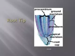
GE MRI tip application

E N D
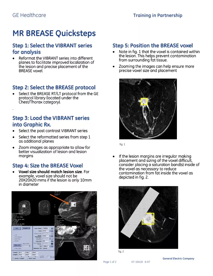
GE Healthcare Training in Partnership MR BREASE Quicksteps MR BREASE Quicksteps Step 1: Select the VIBRANT series Step 1: Select the VIBRANT series for analysis for analysis •Reformat the VIBRANT series into different planes to facilitate improved localization of the lesion and precise placement of the BREASE voxel. BREASE voxel. Step 5: Position the BREASE voxel Step 5: Position the BREASE voxel •Note in fig. 1 that the voxel is contained within the lesion. This helps prevent contamination from surrounding fat tissue. from surrounding fat tissue. •Zooming the images can help ensure more precise voxel size and placement precise voxel size and placement •Note in fig. 1 that the voxel is contained within the lesion. This helps prevent contamination •Reformat the VIBRANT series into different planes to facilitate improved localization of the lesion and precise placement of the •Zooming the images can help ensure more Step 2: Select the BREASE protocol Step 2: Select the BREASE protocol •Select the BREASE RT/LT protocol from the GE protocol library (located under the Chest/Thorax category). Chest/Thorax category). . . •Select the BREASE RT/LT protocol from the GE protocol library (located under the •If the lesion margins are irregular making placement and sizing of the voxel difficult, consider placing a saturation band(s) inside of the voxel as necessary to reduce contamination from fat inside the voxel as depicted in fig. 2. depicted in fig. 2. Step 3: Load the VIBRANT series into Graphic Rx. into Graphic Rx. •Select the post contrast VIBRANT series •Select the post contrast VIBRANT series •Select the reformatted series from step 1 as additional planes as additional planes •Zoom images as appropriate to allow for better visualization of lesion and lesion margins margins Step 3: Load the VIBRANT series •Select the reformatted series from step 1 fig. 1 •Zoom images as appropriate to allow for better visualization of lesion and lesion •If the lesion margins are irregular making placement and sizing of the voxel difficult, consider placing a saturation band(s) inside of the voxel as necessary to reduce contamination from fat inside the voxel as Step 4: Size the BREASE Voxel Step 4: Size the BREASE Voxel •Voxel sizeshould match lesion size. For example, voxel size should not be 20X20X20 mms if the lesion is only 10mm in diameter in diameter •Voxel sizeshould match lesion size. For example, voxel size should not be 20X20X20 mms if the lesion is only 10mm fig. 2 General Electric Company Page 1 of 2 07-10418 6-07
GE Healthcare IMPORTANT- On 1.5T - If User CV 18 is set to 7 in the protocol, 6 SAT bands are automatically selected and applied in the S/I/R/L/A/P positions around the voxel. A maximum of 4 additional sat bands can be graphically applied. If more than 4 additional sat bands are applied manually in graphic Rx, the software will systematically begin to erase those applied by CV18 to help ensure that the maximum of 10 sat bands is not exceeded. On 3.0T - a maximum of 6 SAT pulses may be applied. If manual graphic placement of SAT bands within the voxel is desired to reduce contamination from fat signal, adjust the user CV 18 setting to apply the additional sat bands in positions around the voxel other than those that were manually prescribed. Training in Partnership Step 7: Check center frequency and line width in manual pre-scan line width in manual pre-scan •Check line width (<15 for 1.5T and <30 for 3.0T) •If line width exceeds recommendations, repeat Auto Prescan •Select [Manual Prescan] •Select CF Fine •Select the receiver which provides the highest signal •Adjust center frequency to center on the water peak •Scan Step 7: Check center frequency and • Run [Auto Prescan] Step 6: Optimize SNR via proper NEX selection NEX selection artifacts related to patient motion. 1.5Tesla Voxel size NEX 20x20x20mm 32NEX 18x18x18mm 56NEX 15x15x15mm 82NEX 10x10x10mm 128NEX 3.0 Tesla Voxel size NEX Scan Time 20x20x20mm 32NEX 18x18x18mm 32NEX 15x15x15mm 56NEX 10x10x10mm 82NEX Step 6: Optimize SNR via proper •Update the NEX as appropriate. The chart below contains recommendations based on voxel size. •In order to maintain good SNR, NEX should be adjusted in relation to voxel size. Keep in mind however that an increase in NEX will also will increase scan time and therefore increase the potential for Scan Time 4:48 min 8:00 min 11:20 min 17:36 min 4:48 min 4:48 min 8:00 min 11:20 min General Electric Company Page 2 of 2 07-10418 6-07