Download
1 / 4
40 likes | 112 Views
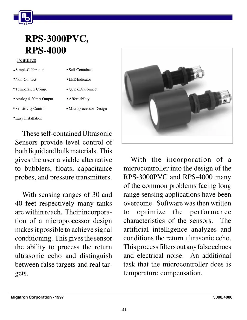
Simple Calibration<br>· Non-Contact<br>· Temperature Comp.<br>· Sensitivity Control<br>· Level Sensor<br>· Self-Contained<br>· LED Indicator<br>· Quick Disconnect<br>· Level Control<br>· Microprocessor Design<br><br> Model Number: RPS-3000PVC / RPS-4000

E N D
RPS-3000PVC, RPS-4000 Features Simple Calibration Self-Contained Non-Contact LED Indicator Temperature Comp. Quick Disconnect Analog 4-20mA Output Affordability Sensitivity Control Microprocessor Design Easy Installation These self-contained Ultrasonic Sensors provide level control of both liquid and bulk materials. This gives the user a viable alternative to bubblers, floats, capacitance probes, and pressure transmitters. With the incorporation of a microcontroller into the design of the RPS-3000PVC and RPS-4000 many of the common problems facing long range sensing applications have been overcome. Software was then written to optimize the performance characteristics of the sensors. The artificial intelligence analyzes and conditions the return ultrasonic echo. This process filters out any false echoes and electrical noise. An additional task that the microcontroller does is temperature compensation. With sensing ranges of 30 and 40 feet respectively many tanks are within reach. Their incorpora- tion of a microprocessor design makes it possible to achieve signal conditioning. This gives the sensor the ability to process the return ultrasonic echo and distinguish between false targets and real tar- gets. Migatron Corporation - 1997 3000/4000 -41-
HOW TO CALIBRATE The following is a brief list of features for the RPS- 3000PVC and RPS-4000. Method One (and possibly the most direct way to calibrate the sensing range) is as follows (see figure B): SIMPLE CALIBRATION: The sensing window can be adjusted by using one of three easy methods. NOTE: When the sensors are powered up and the control lines not used, they are factory preset to maximum range. Step 1: Tie the Red/Yel wire (20mA control line) and the Red/Blue wire (4mA control line) together. NON-CONTACT: The use of ultrasonic sound to measure distance means that the sensor does not need to come in contact with the target. Step 2: With the material level at the 4mA point, usually the low level, connect these lines to ground (Green wire) for one second. TEMPERATURE COMPENSATED: This is accomplished by means of a temperature probe that is built into the transducer head. Step 3: With the material level at the 20mA point, usually the high level, connect these lines to plus (Red wire) for one second. ANALOG OUTPUT: These sensors provide a 4-20mA analog output that is proportional to the changing distance. This output can be inverted. The sensor is now calibrated and will generate the analog 4-20mA output between these two points. NOTE: When completed, the two control lines should remain tied together. To change the window, disconnect these two wires for one second and then reconnect them. Then repeat steps 2 and 3. The far point should always be programmed first, then the near point. SENSITIVITY CONTROL: This enables the gain of the sensor to be adjusted to work best in different tanks and on different materials. EASY INSTALLATION: Both of these sensors are con- tained in a standard 30mm housing. They come with two jam-nuts for simple mounting. Method Two calibrates the sensors by using the following charts (see figure C): RPS-3000PVC Sensing Red/Blue Red/Yel Wire Wire Window OPEN LOW HIGH OPEN LOW HIGH OPEN LOW HIGH RPS-4000 SELF-CONTAINED: There are no remote boxes to mount with these sensors. All necessary electronics are con- tained within the sensor. Red/Blue Wire Sensing Window 2' - 40' 2' - 36' 2' - 32' 2' - 28' 2' - 24' 2' - 20' 2' - 16' 2' - 12' 2' - 8' Red/Yel Wire 2' - 30' 2' - 27' 2' - 24' 2' - 21' 2' - 18' 2' - 15' 2' - 12' 2' - 9' 2' - 6' OPEN OPEN OPEN LOW LOW LOW HIGH HIGH HIGH OPEN LOW HIGH OPEN LOW HIGH OPEN LOW HIGH OPEN OPEN OPEN LOW LOW LOW HIGH HIGH HIGH LED INDICATOR: This indicates the detect state of the sensor as well as the strength of the return echo. This feature helps to insure proper alignment during installation. AFFORDABILITY: These sensors were designed to be cost competitive and to solve applications. MICROPROCESSOR DESIGN: The incorporation of a microprocessor allowed software to be written to solve many of the common problems that needed to be overcome with long range applications. Open: This indicates that the control line is not tied to anything. It is left floating. High: The control line is tied to plus (Red Wire). Low: The control line is tied to ground (Green Wire). When using these charts to calibrate the sensors the analog output will occur over the full range of the selected sensing window. The 20mA will be at the near distance and the 4mA will be at the far distance. One advantage of calibrating the sensors this way is that there is no need to fill the tank to the high and low limits. Another advantage is that once the sensor is installed there is no need to go back to it to program. This can be done at a remote location at the end of the sensor's cable. Migatron Corporation - 1997 3000/4000 -42-
target, the gain can be reduced to see if the false target disappears. Method Three calibrates the sensors by using resistors tied to the control lines (see figure D). These resistors are installed between the control lines and ground (green wire). The following resistance formula applies for distance: LED INDICATOR 1Kohm = 1 foot. The LED is located at the back of the sensor. It provides by way of color various indication as to the sensor's functions. Its primary purpose is to insure proper alignment during installation. The following colors indicate: For example if a range of 5' to 15' is desired with an analog output of 20mA at 5', and 4mA at 15', the following resistor values should be selected: Green: The sensor has power and is in the no-detect state. 15' = 15Kohm resistor tied to 4mA control line (Red/Blue) 5' = 5Kohm resistor tied to 20mA control line (Red/Yellow) Yellow: The sensor has detected a target but is receiving a weak signal. It may be that the sensor is not properly aligned to the material or that the target is providing a weak return echo. The output will now start at 5' 20mA and decrease with distance to 15' 4mA. The output can be scaled in the opposite direction by reversing the values: Red: This indicates that the sensor is detecting the target. The brighter the shade of red the stronger the return echo. This indicates the sensor is properly aligned and the target is providing a good reflective surface. 5' = 5Kohm resistor tied to 4mA control line (Red/Blue) 15' = 15Kohm resistor tied to 20mA control line (Red/Yel) The output now starts at 5' 4mA and increases with distance to 15' 20mA. NOTE: It may not always be possible to get a bright red signal. This is because various materials will have different reflectivity characteristics. However, as long as the sensor stays in the yellow to red state, enough return signal is being received and the sensor will function properly. Potentiometers can be used in place of fixed resistors and then the proper distances can be dialed in. The advantage with this method, as with the second way of calibrating, is that the tank does not need to be filled to its high and low limits during setup. In addition these set points can be adjusted at a later time without going to the top of the tank. ANALOG OUTUT The RPS-3000PVC and RPS-4000 provide an analog cur- rent output of 4-20mA. This output is proportional to the changing distance that has been programmed. The output load rating of the sensors are 0 to 500 ohms. HOW TO USE THE GAIN CONTROL The RPS-3000PVC and RPS-4000 sensors provide the user with gain control. This is controlled by the Red/White wire (see figure E). When this wire is left open (floating) the sensors are operating at their maximum sensitivity. The sensor's gain can be reduced by doing the following: QUICK DISCONNECT CONNECTOR At the rear of the sensor, there is a water tight quick disconnect connector. This allows the sensor to be easily removed from the tank should this be desired. Install a 100Kohm potentiometer or a fixed value resistor across the gain control line (Red/White wire) and ground (Green wire). With the potentiometer set at 100Kohm, the gain or sensitivity of the sensor is at its maximum. When the potentiometer is set at 75Kohm, the sensitivity is 75% of full gain. If the potentiometer is turned all the way down which is equivalent to shorting the gain wire to ground, the sensor is at minimum sensitivity. MICROPROCESSOR DESIGN The RPS-3000PVC and RPS-4000 long range ultrasonic sensors incorporate a high speed microcontroller/micro- processor. Software was then written to optimize the performance characteristics of the sensors. This artifical intelligence analyzes and conditions the return ultrasonic echo. This process filters out any false echos and electrical noise. An additional task that the microcontroller does is temperature compensation. This allows the sensor to have a more accurate output over varying temperature ranges. Thus with the incorporation of a microcontroller many of the common problems facing long range sensing applications have been overcome. The sensitivity/gain control allows the sensor to be adjusted to work best in different tanks and on different materials. This control does not need to be used. If the sensor is installed and works well with full sensitivity there is no need to reduce the gain. However if the sensor is installed and it seems to be detecting something other then the desired Migatron Corporation - 1997 3000/4000 -43-
Specifications: The angle of tilt of a flat target is plus and minus 10 degrees. The Beam Spread is approximately 20 degrees. This is equal to 4.25" per foot. Operational Range: RPS-3000PVC Adjustable 2' to 30' RPS-4000 Adjustable 2' to 40' Power Input: 20 - 30 VDC Reverse Polarity Protected Input Current: 125 Milliamps Ambient Temperature: -20ºC to 60ºC or -5ºF to 140ºF 20 20 Humidity: 0% - 95% Non-Condensing Enclosure: housing with PVC sensing face. RPS-4000: Epoxy filled PVC housing with Glass Reinforced Epoxy sensing face. RPS-3000PVC: Epoxy filled PVC CORRECT CORRECT Outputs: Current Sourcing Analog Output 4 - 20mA Inverted & Non-Inverted Short Circuit Protected Transducer Frequency: RPS-3000PVC PRS-4000 38Khz 41Khz 20 20 Transmit Time: This equals the sensors maximum distance x 10mSec. For example if the maximum programmed distance is 10' the transmit time is 100mSec. CORRECT INCORRECT Fig. A Weight: 15 ounces RED 20-30VDC RED 20-30VDC RED 20-30VDC RED 20-30VDC GREEN GROUND RED/BLK 4-20mA GREEN GROUND RED/BLK 4-20mA RED/WHT GAIN CONTROL GREEN GROUND RED/BLK 4-20mA RED/WHT GAIN CONTROL GREEN GROUND RED/BLK 4-20mA RED/WHT GAIN CONTROL RED/WHT GAIN CONTROL RED/BLU 4mA CONTROL LINE RED/BLU 4mA CONTROL LINE RED/BLU 4mA CONTROL LINE TIE HIGH, LOW, OR OPEN TAP HIGH LOW RED/BLU 4mA CONTROL LINE RED/YEL 20mA CONTROL LINE RED/YEL 20mA CONTROL LINE RED/YEL 20mA CONTROL LINE TIE HIGH, LOW, OR OPEN RED/YEL 20mA CONTROL LINE Fig. B Fig. C Fig. E Fig. D Figure: 6.625" 5 1 6 A - Installation / Beam Spread B - Wiring Diag. for programming method #1 C - Wiring Diag. for programming method #2 D - Wiring Diag. for programming method #3 E - Wiring Diag. for gain control F - Connector Diagram (Male View) G - Mounting Dimensions "QD" cables are sold separately. 2 4 Thread M30 x 1.5 3 2.750" 1. Red-Wt. Tr 2. Red 3. Green 4. Red-Yl. Tr 5. Red-Bk. Tr 6. Red-Blu. Tr Fig. F Fig. G PART NUMBER RANGE DESCRIPTION PVC Housing with PVC Sensing Face 2' to 30' RPS-3000PVC PVC Housing with Glass Reinforced Epoxy Sensing Face 2' to 40' RPS-4000 5000127-2 6' Cable with "QD" 5000127-4 16' Cable with "QD" (815) 338-5800 / FAX: (815) 338-5803 Migatron Corp. 935 Dieckman Rd., Woodstock, Il. 60098 USA http://www.migatron.com e-mail: info@migatron.com -44-