Download
1 / 17

E N D
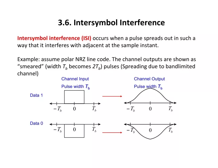
3.6. Intersymbol Interference Intersymbol interference (ISI) occurs when a pulse spreads out in such a way that it interferes with adjacent at the sample instant. Example: assume polar NRZ line code. The channel outputs are shown as “smeared” (width Tb becomes 2Tb) pulses (Spreading due to bandlimited channel) Channel Input Pulse width Tb Channel Output Pulse width Tb Data 1 b T b T b T − b T − 0 0 Data 0 b T b T − 0 b T b T − 0
3.6. Intersymbol Interference He(t) ⎡ ⎣⎢ ⎤ ⎦⎥*he(t) win(t)=π anh(t−nTs) n∑ wout(t)= anδ(t−nTs) n∑ he(t)= h(t)*hT(t)*hC(t)*hR(t) wout(t)= anhe(t−nTs) n∑ ℑ He( f )= H( f )HT( f )HC( f )HR( f ) ⎡ ⎢ ⎢ ⎤ ⎥ ⎥=Ts ⎛ ⎜⎜ ⎞ ⎟⎟ ⎛ ⎜⎜ ⎞ ⎟⎟ sinπTsf πTsf t H( f )=ℑ Π where Ts ⎝ ⎠ ⎝ ⎠ ⎣ ⎦
3.6. Intersymbol Interference Example 3-13 Intersymbol Interference Caused by RC Filtering Plot the output waveform when a channel filters a unipolar NRZ signal. Assume that the overall filtering effect of the transmiIer, channel, and the receiver is that of an RC-low pass filter where the 3 dB bandwidth is 1 HZ. Assume that the unipolar NRZ input signal has a bit rate of Rb = 1 HZ and that the data on the unipolar NRZ signal is [1 0 0 1 0 1 1 0 1 0]. Plot the waveform at the receiver output and observe the intersymbol interference.
3.6. Intersymbol Interference Example 3-13 Intersymbol Interference Caused by RC Filtering
3.6. Intersymbol Interference • Nyquist three criteria – Pulse amplitudes can be detected correctly despite pulse spreading or overlapping, if there is no ISI at the decision- making instants • 1: At sampling points, no ISI • 2: At threshold, no ISI • 3: Areas within symbol period is zero, then no ISI – At least 14 points in the finals • 4 point for questions • 10 point like the homework
3.6. Intersymbol Interference Nyquist’s First Method (Zero ISI) Nyquist’s first method for eliminaWng ISI is to use an equivalent transfer funcWon He(f): ⎧ ⎨ ⎩⎪ C, k =0 fs=1 ⎛ ⎜⎜ ⎞ ⎟⎟ ⎪ He( f )=1 f fs he(kTs+τ)= where Π Ts fs 0, k ≠0 ⎝ ⎠ He(f) 1/fs he(t)=sinπ fst π fst f fs/2 0 -fs/2
3.6. Intersymbol Interference Nyquist’s First Method (Zero ISI) This type of pulse will allow signaling at a baud rate of D=1/Ts=2B (for Binary R=D) sf Absolute bandwidth is: B MINIMUM BAND W ID TH = 2 = Signaling Rateis: D =1 T 2 B Pulses/se c s
3.6. Intersymbol Interference Nyquist’s First Method (Zero ISI) This type of pulse will allow signaling at a baud rate of D=1/Ts=2B (for Binary R = D) He(f) 1/fs he(t) f fs/2 0 -fs/2 ² Since pulses are not possible to create due to: Infinite Wme duraWon. Sharp transiWon band in the frequency domain. ² The Sinc pulse shape can cause significant ISI in the presence of Wming errors. If the received signal is not sampled at exactly the bit instant (SynchronizaWon Errors), then ISI will occur.
3.6. Intersymbol Interference Nyquist’s First Method (Zero ISI) THEOREM:A filter is said to be a Nyquist filter if the effecWve transfer funcWon is: f 2 f0 ⎝ ⎠ ⎨ ⎪ ⎪ ⎧ ⎪⎪ ⎛ ⎜⎜ ⎞ ⎟⎟+Y( f ), f < 2 f0 Π He( f )= 0, elsewhere ⎩ Y(f) is a real funcWon and even symmetric about f = 0; Y(f) = Y(-f), |f| < 2f0 Y is odd symmetric about f = f0; Y(-f + f0) = Y(-f + f0), |f| < 2f0 There will be no intersymbol interference at the system output if the symbol rate is: D = fs = 2f0
3.6. Intersymbol Interference Y f Y ( ) is a real function and even symmetric about = 0: ( ), 2 Y is odd symmetric about f f f Y f f f ( ) − = < 0 f : = 0 Y f f Y f ( f ), f f ( ) − + = − + < 0 0 0
3.6. Intersymbol Interference A more general class of filter: Raised Cosine-Rolloff Filter ⎧ ⎪ ⎪ ⎪⎪ 1, f < f1 ⎧ ⎪ ⎫ ⎬ ⎭⎪ ⎡ ⎢ ⎢ ⎤ ⎥ ⎥ ( ) f − f1 2 fΔ π ⎪ He( f )= 1/ 2 1+cos ⎨ ⎩⎪ , f1< f < B ⎨ ⎪ ⎪ ⎪ ⎪ ⎣ ⎦ 0, f > B ⎩ Where B is the absolute bandwidth and the parameters fΔ= B− f0 and f1= f0− fΔ f0 is the 6-dB bandwidth of the filter. The rolloff factor is defined to be r =fΔ f0
3.6. Intersymbol Interference A more general class of filter: Raised Cosine-Rolloff Filter ⎡ ⎢ ⎢⎢ ⎤ ⎥ ⎥⎥ ⎛ ⎜⎜ ⎞ ⎟⎟ sin2π f0t 2π f0t cos2π fΔt 1− 4 fΔt ( he(t)=ℑ−1He( f ) ⎡⎣ ⎤⎦= 2 f0 2 ) ⎝ ⎠ ⎣ ⎦
3.6. Intersymbol Interference A more general class of filter: Raised Cosine-Rolloff Filter Frequency response and impulse responses of Raised Cosine pulses for various values of the roll off parameter. r B ↑ → ↑ r ISI ↑ → ↓
3.6. Intersymbol Interference A more general class of filter: Raised Cosine-Rolloff Filter ⎧ ⎪ ⎪ ⎪⎪ 1, f < f1 ⎧ ⎪ ⎫ ⎬ ⎭⎪ ⎡ ⎢ ⎢ ⎤ ⎥ ⎥ ( ) f − f1 2 fΔ π ⎪ He( f )= 1/ 2 1+cos ⎨ ⎩⎪ , f1< f < B ⎨ ⎪ ⎪ ⎪ ⎪ ⎣ ⎦ 0, f > B ⎩ D =2B Baud rate: 1+r Where B is the absolute bandwidth of the system and r is the system rolloff factor.
3.6. Intersymbol Interference Problem 3.49 Assume that a pulse transmission system has the overall raised cosine-rolloff Nyquist filter characterisWc described by ⎧ ⎪ ⎪ ⎪⎪ 1, f < f1 ⎧ ⎪ ⎫ ⎬ ⎭⎪ ⎡ ⎢ ⎢ ⎤ ⎥ ⎥ ( ) f − f1 2 fΔ π ⎪ He( f )= 1/ 2 1+cos ⎨ ⎩⎪ , f1< f < B ⎨ ⎪ ⎪ ⎪ ⎪ ⎣ ⎦ 0, f > B ⎩ ⎧ ⎪⎪ ⎛ ⎜⎜ ⎞ ⎟⎟+Y( f ), f Find the Y(f) Nyquist funcWon of f < 2 f0 Π 2 f0 He( f )= ⎨ ⎪ ⎪ ⎝ ⎠ 0, elsewhere ⎩
3.6. Intersymbol Interference Problem 3.50 An analog signal is to be converted into a PCM signal that is a binary polar NRZ line code. The signal is transmiIed over a channel that is absolutely bandlimited to 4 kHz. Assume that the PCM quanWzer has 16 steps and that the overall equivalent system transfer funcWon is of the raised cosine-rolloff type with r = 0.5. a.) Find the maximum PCM bit rate that can be supported by this system without introducing ISI. b.) Find the maximum bandwidth that can be permiIed for the analog signal.
