Download
1 / 22
230 likes | 642 Views
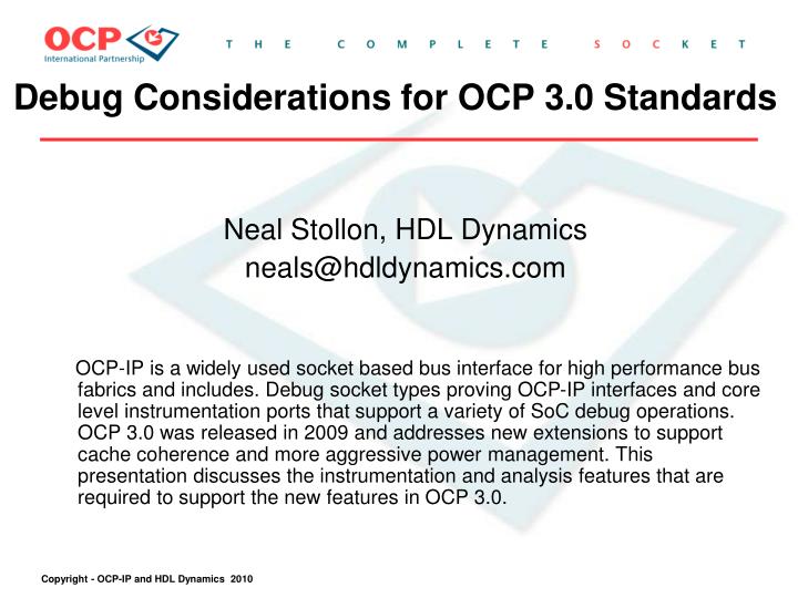
Debug Considerations for OCP 3.0 Standards. Neal Stollon, HDL Dynamics neals@hdldynamics.com

E N D
Debug Considerations for OCP 3.0 Standards Neal Stollon, HDL Dynamics neals@hdldynamics.com OCP-IP is a widely used socket based bus interface for high performance bus fabrics and includes. Debug socket types proving OCP-IP interfaces and core level instrumentation ports that support a variety of SoC debug operations. OCP 3.0 was released in 2009 and addresses new extensions to support cache coherence and more aggressive power management. This presentation discusses the instrumentation and analysis features that are required to support the new features in OCP 3.0.
OCP-IP Overview OCP 2.x Socket • Open Core Protocol (OCP) is open standard for intellectual property (IP) core interfaces, or sockets, • "plug and play" SoC design • Widely used in major ICs • IP is International Partnership - . consortium supporting OCP • 50+ active members • tools, IP infrastructure • Research Community • Working groups in ESL, verification debug, . . . see www.ocpip.org OCP Fabric RISC Mem Ctrlr DSP RAM Other IP Other IP Standardized transfer socket Master or slave, with options for bursting, threading, reordering
OCP General Features • OCP supports range of sophisticated bus interface capabilities …which also translates into a lot of bus complexity • 64-bit read and write data busses • 32-bit multiple mode addresses • Multiple Outstanding transactions • Multiple Command and Response types • Multiple User defined signals • Single or Bursted Reads and Writes • Single Request Multiple Data • Multiple synchronous core to bus ratios • Data Ordering and reordering using tags • Bus visibility helps get complex applications running right
OCP Debug Working Group • WG focus to define debug signaling between cores and OCP subsystems • Debug interfaces follow socket based OCP Protocol for SoC IP connection • Leverage other work for IOs (JTAG, Nexus, MCDS), APIs, etc. • Defined subset architecture and signaling for on-chip core and bus debug Baseline Sockets 1149.1 JTAG Debug resets Generic Processor debug handshakes Synchronized Trace/Debug Trace Triggers Cross Trigger Interfaces TimeStamp Interfaces Power Management Debug Security OCP 2.1 Socket OCP Debug Socket OCP Fabric b OCP Fabric RISC RISC Mem Ctrlr Mem Ctrlr DSP DSP RAM RAM Other IP Other IP Other IP Other IP not be same Debug Features For all sockets are optional Standardized transfer socket Master or slave, with optional bursting, thread signals
OCP Multi-Core Debugging Socket • OCP-IP Debug WG announced the release of its Debug Standard 1.0 in 2007 • Basic and Extended sets of socket level debug signals • SoC level Interface uses standard 1149.1 JTAG/ 5001 Nexus • Debugging of multiple processor cores connected with OCP interface. • Allows designers to distribute debug signals as part of system interface scheme • Ability to set up multi-core debug hardware and software using standard signal interfaces
Debug-IP HW connections to SoC: 1 CORE-INTERFACE: interfaces to core IP-block debug data/control proprietary IO 2 BUS-INTERFACE: interface to a bus traffic [event/trace data collect, compression and triggering] 3 CROSS-TRIGGER INTERFACE: to other debug-IP blocks [event-synch.] 4 PIN-INTERFACE CONTROL: IF to JTAG for debug control to analyzer/debugger software. 5 PIN-INTERFACE DATA: interface for high speed data [like Nexus] Debug software API for information transfer and display: A. System Debug SW API interface B. EDA API interface – block / system level verification (ESL, RTL) CHIP Cross trigger IF 3 OCP Bus fabric Bus test socket 1 Core Debug IF Trace IF 2 Memory-mapped JTAG-mapped Nexus-mapped Debug-IP registers Debug IF 4 5 Nexus data-trace JTAG control Debug Software SYS API EDA API A B Debug Hardware Environment
OCP Debug Hardware Basic Socket • Debug Control Socket • ReqDebugX - input • MsuspendX - output • DebugerrorX - output • DebugConX - input • NoSRespX - output • ForceRespX - input • ForceAbortX - input • ForceAbortAckX - output • Triggering Socket • TrigY_Cond (m:0) - input • TrigY_En (m:0) - input • TrigY_Action(n:0) - output • TrigY__En (n:0) - output • Ext_trig_CLK - input • Ext_Cond - input • Ext_Action - output 1149.1 compliant Interface TCK, TRST TMS, TDI, TDO Nexus Interface Aux In/Out (for trace)
OCP 3.0 Debug Issues • OCP 3.0 specification adds • Cache Coherence • Advanced Power Management • Debug WG challenge • Low overhead debug for different cache coherence (Directory, Snoop based) architectures • How to debug power management issues • How to prevent power management from messing with debug
Debug of Cache Coherent Systems DIRECTORY BASED ARCHITECTURE • Access Cache Address for cached regions • Check directory flags for data modification. • On update cache, update or clear directory flags • User defined directory memory range granularity • Directory acts as a • coherent slave when receiving requests from • coherent masters and • coherent master when sending requests to • coherent slaves. • Debug Issues: • Debuggers need to know which and when • cache update is running while blocking main bus. • Triggers need to account for delay due to • cache access and cache update • Directory flag changes may be transparent to debugger. • Refresh of cache with data, blocks the bus and should • be observable by debugger.
Debug of Cache Coherent Systems SNOOP-BUS BASED ARCHITECTURE • Access Cache Address for cached regions • Poll masters/slaves for changed values • updated value into cache and use it. • Broadcasting memory address value changes • Coherence between caches/ memory • restored prior to the cache value use • Broadcasting substitutes for flag directory. • Debug issues • Delay for cache coherence broadcast / update • Broadcasting may be transparent to debug. • Propagation for cache value update is blocking • main bus needs to be observable by debugger • Debuggers need to know which and when cache • refreshes occur, • Relationship to blocking the system data bus.
Debug of Cache Coherent Systems The good news In either case - Information on cache refresh can be deduced from OCP coherence extensions (OCPce) port coherence refresh control signals - MCohCmd, MReqInfo - SCohState, SThreadBusy, - MThreadBusy, MDataThreadBusy
Types of instrumentation needed • On-chip or off-chip transaction trace • Filtered data trace mode • Coherent Core access to on-chip trace buffer • PC trace access for stalls • Performance counters to monitor caching isses
Debug Based on OCP Intervention interface OCP signals enabling a single-threaded, non-blocking OCP interface,and supporting OCP intervention interface.
An OCP Coherent (Directory based) System • Several Approaches being investigated : • Trace analysis of cache signals • Definition of performance counters • Reuse of verification done of coherent systems as debug suite Points for signal Monitoring or trace
OCP 3.0 Debug Issues • OCP 3.0 specification adds • Cache Coherence • Advanced Power Management • Debug WG challenge • Low overhead debug for different cache coherence (Directory, Snoop based) architectures • How to debug power management issues • How to prevent power management from messing with debug
Master Driven Power Management • OCP defines a FSM based Power Down Sequence for each Master. • Many masters, each powering down and up on their own schedules, adds significant complexity of analysis complexity
OCP disconnect protocol signals Each OCP Master has it own Power Management FSM Adds diverse debug scenarios
Table 2: OCP Inter-Core Connection Interfaces • Debug Socket may be defined as a master “alternate behavior” Port. • Allows Debug blocks to be • powered down if not in use • Allows ongoing debug activity • to stall power down sequence
OCP Debug Socket Options • From connection pov, Debug Socket may be instantiated as • Master in itself + Allows independent Power down sequence when not used. + Debug operations occur independently of other concurrent operation - Additional logic overhead associated with OCP Master • Master “alternate behavior” Port in embedded in an OCP Master + ongoing debug activity can stall power down sequence - Power down does not occur unless entire Master powers down • Slave + Simple, allows some debug (triggering as example) operations to be implemented by the (Programmable) master - Relies on a Master to determine power down
OCP 3.0 Debug - WIP Debug Development for OC_ 3.0 is still work in progress Points the way to debug issues that will be faced in many emerging SoC Architectures OCP 3.0 support addendum to OCP Debug Spec planned for EOY 2010