Download
1 / 3
0 likes | 8 Views
The method of extraction described herein makes certain the biological accelerator that causes the complete combustion is effectively gathered by the sterilizer promptly. Furthermore, no important polypeptide will be lost. Coordinated electromagnetic functioning removes burning issues, however certain types of antagonists remain pyrophoric along with can cause unexpected burns in the immediate environment.

E N D
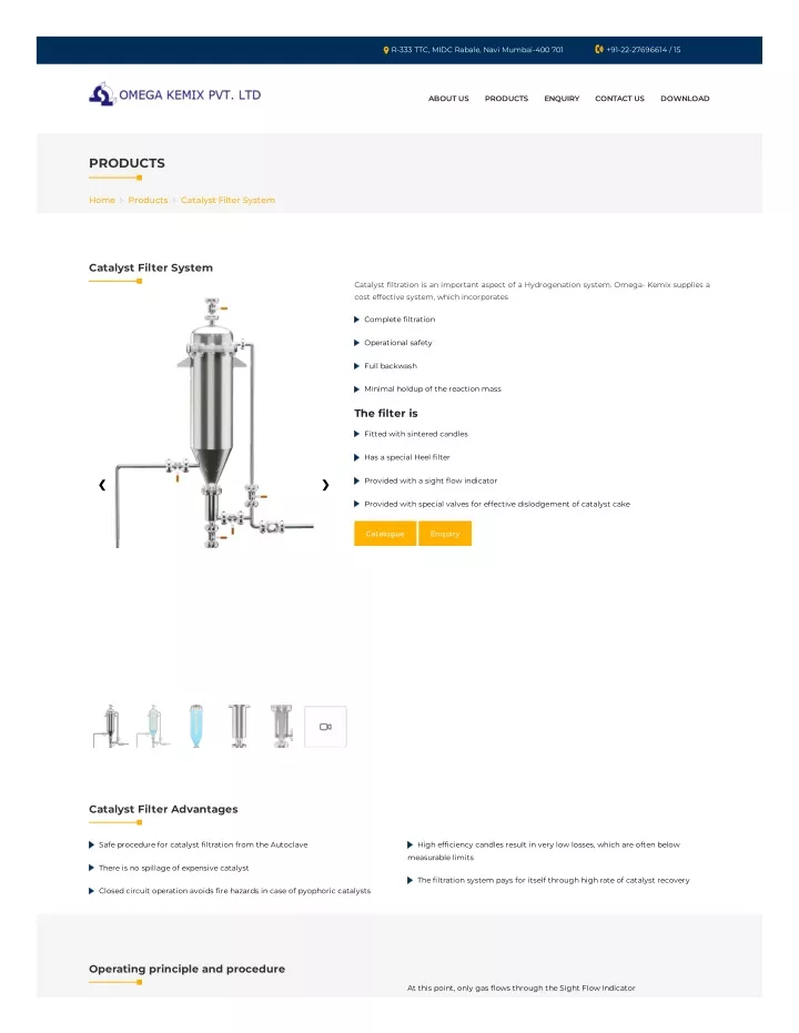
R-333 TTC, MIDC Rabale, Navi Mumbai-400 701 +91-22-27696614 / 15 ABOUT US PRODUCTS ENQUIRY CONTACT US DOWNLOAD PRODUCTS Home Products Catalyst Filter System Catalyst Filter System Catalyst ?ltration is an important aspect of a Hydrogenation system. Omega- Kemix supplies a cost effective system, which incorporates Complete ?ltration Operational safety Full backwash Minimal holdup of the reaction mass The ?lter is Fitted with sintered candles Has a special Heel ?lter Provided with a sight ?ow indicator ❮ ❯ Provided with special valves for effective dislodgement of catalyst cake Catalogue Enquiry Filtration and Catalyst system Supplier, Manufacturer and Supplier of catalyst ?ltration from the Autoclave, Catalyst Filter System, ?re hazards in case of pyrophoric catalysts, ?re hazards in case of pyrophoric catalysts India, gas liquid induction reactors in mumbai, gas liquid induction reactors in india, gas liquid induction reactor manufacturers in mumbai, gas liquid induction reactor manufacturers in India, Chemical reaction in viscous liquids and slurries suppliers , Chemical reaction in viscous liquids and slurries suppliers in mumbai ,Chemical reaction in viscous liquids and slurries suppliers in India Catalyst Filter Advantages Safe procedure for catalyst ?ltration from the Autoclave High ef?ciency candles result in very low losses, which are often below measurable limits There is no spillage of expensive catalyst The ?ltration system pays for itself through high rate of catalyst recovery Closed circuit operation avoids ?re hazards in case of pyophoric catalysts Operating principle and procedure At this point, only gas ?ows through the Sight Flow Indicator
Catalyst ?ltration is an important aspect of a Hydrogenation system. Omega ‐ A Zero Holdup Filter is ?tted at the lower end of the Main Filter, below the Kemix supplies a cost effective system, which incorporates complete ?ltration, conical portion. This is a Jacketed Sintered pipe (or Lower Candle), around 125 operational safety, full backwash, as well as minimal holdup of the reaction mass mm inside diameter, suitable for inside to outside ?ltration. Please refer Drawing 2 for details of the Zero Holdup Filter. At the completion of hydrogenation reaction, balance Hydrogen gas in reactor headspace is vented, and the Reactor is purged with Nitrogen, to eliminate all When gas ?ow (i.e., no liquid ?ow) is observed through the Sight Flow indicator traces of remaining Hydrogen. Subsequently, the Reactor is pressurized to about as described above, Valve V is closed, and V is opened. Nitrogen gas entering 4 9 1 bar with Nitrogen, through Valve V Valves V , V and V are opened. All othe 1 the Filter cone forces ?ltrate through the Lower Candle, so that slurry in the 2 3 4 valves (V to V8) are in closed position. Nitrogen is continuously fed through 5 Filter Cone and lower parts is ?ltered through the Zero Holdup Filter. Heel ?ltrate Valve V1, so that Reactor pressure is maintained around 1 bar. is observed ?owing through the Sight Flow Indicator FI. Typically, if the catalyst is noble metal on a carrier, e.g., Pd/C, the entire mass is Once the entire heel slurry is ?ltered, no further liquid ?ow is observed through ?ltered. In this case, it is advisable to stir the reaction mass at around 50 RPM, the Sight Flow Indicator. All the slurry has been ?ltered. At this stage, outer and the dip pipe or blow leg should extend to the lowest possible point in the surfaces of the upper candles, and inner surface of the lower candle are covered Reactor. with wet cake. Valves V , V and V and V are now closed, and the Reacto vented 9 3 2 1 to atmospheric pressure, by opening Valve V . Solvent/feed for the next batch, or 10 For heavy metal catalysts like Raney Nickel, the bulk of the catalyst settles within Nitrogen at 1 to 5 bar is introduced at Valve V , located at the top of the Filter. 5 a very short time, typically 30 minutes after cessation of stirring. In this case, a Keeping Valve V open, Valve V and then Valve V is opened, so that catalyst 10 8 6 common practice is to ?lter the supernatant liquid (through a dip pipe adhering to candle surfaces gets back‐?ushed into the Reactor. terminating just below the lower tan line of the Reactor). For best results, Valve V should be a Solenoid operated ball valve, so that there is 6 Nitrogen pressure in the Reactor headspace forces the liquid‐catalyst slurry into a pressure pulse while opening this valve. This ensures effective dislodgement of the Main Filter through Valve V . This ?lter is ?tted with sintered SS 316 L candles, 3 catalyst cake from the Candles. suspended from a tubesheet. This procedure ensures a safe procedure for catalyst ?ltration from the Initially, the Filter body ?lls up with Liquid‐catalyst slurry. When it is full, ?ltration Autoclave. There is no spillage of expensive catalyst. The closed circuit operation commences. Catalyst cake accumulates outside the candles. Clear ?ltrate enters avoids ?re hazards, as many catalysts are pyrophoric, and can spontaneously the candles, and ?ows out through Valve V . Filtrate ?ow can be observed 4 ignite when exposed to air. High ef?ciency candles result in very low losses, through Sight Flow Indicator (FI). which are often below measurable limits. The ?ltration system pays for itself. Once the Reactor contents are entirely displaced by Nitrogen, gas will ?ow into After several batch cycles, it may be necessary to remove catalyst from the the Filter through V . The Filter Candles are ?tted with an inner Siphon Tube. Gas 3 system, and send it for disposal or regeneration. In this case, Valve V is opened 7 entering the Filter displaces the slurry, so that clear liquid is siphoned out instead of V , during back ?ushing operation, and spent catalyst collected in the 8 through Valve V due to action of siphon tubes in the candles. Due to this action, 4 Recycle Drum. slurr level in the Filter falls to the lower end of the candles. In effect, the ?lter cone and lower parts are full of un?ltered slurry (also known as "Heel"), and candles are coated with wet cake.
Product Links Quick Links Gas Induction Reactor About Us 022-27696614 / 15 Magnetic Seals Industries Catalyst Filter System Products sales@okpl.com Online Sampling Company journey Gas Induction Reactors Enquiry Downloads R-333 TTC, MIDC Rabale, Navi Mumbai - 400 701 Catalyst Filter Enquiry Training Copyright © OMEGA - KEMIX PVT. LTD... All rights reserved. Designed by: Dreamsoftindia.com