Download
1 / 2
20 likes | 510 Views
RESULTS AND DISCUSSION Fig. 2 shows multiple levels of structural order within micropatterned arrays of cross-linkable, amphiphilic, dendrimer multilayers. The microcontact printing method allowed the film thickness of the nanostructured dendrimer arrays to be controlled. (a) (b)

E N D
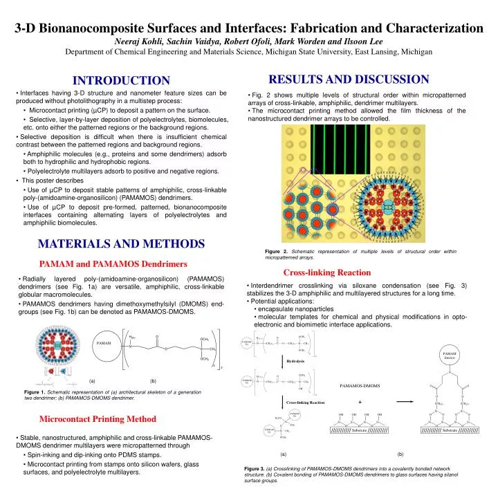
RESULTS AND DISCUSSION • Fig. 2 shows multiple levels of structural order within micropatterned arrays of cross-linkable, amphiphilic, dendrimer multilayers. • The microcontact printing method allowed the film thickness of the nanostructured dendrimer arrays to be controlled. (a) (b) Figure 1.Schematic representation of (a) architectural skeleton of a generation two dendrimer; (b) PAMAMOS-DMOMS dendrimer. Figure 2.Schematic representation of multiple levels of structural order within micropatterned arrays. 3-D Bionanocomposite Surfaces and Interfaces: Fabrication and Characterization Neeraj Kohli, Sachin Vaidya, Robert Ofoli, Mark Worden and Ilsoon Lee Department of Chemical Engineering and Materials Science, Michigan State University, East Lansing, Michigan • INTRODUCTION • Interfaces having 3-D structure and nanometer feature sizes can be produced without photolithography in a multistep process: • Microcontact printing (µCP) to deposit a pattern on the surface. • Selective, layer-by-layer deposition of polyelectrolytes, biomolecules, etc. onto either the patterned regions or the background regions. • Selective deposition is difficult when there is insufficient chemical contrast between the patterned regions and background regions. • Amphiphilic molecules (e.g., proteins and some dendrimers) adsorb both to hydrophilic and hydrophobic regions. • Polyelectrolyte multilayers adsorb to positive and negative regions. • This poster describes • Use of µCP to deposit stable patterns of amphiphilic, cross-linkable poly-(amidoamine-organosilicon) (PAMAMOS) dendrimers. • Use of µCP to deposit pre-formed, patterned, bionanocomposite interfaces containing alternating layers of polyelectrolytes and amphiphilic biomolecules. MATERIALS AND METHODS PAMAM and PAMAMOS Dendrimers Cross-linking Reaction • Radially layered poly-(amidoamine-organosilicon) (PAMAMOS) dendrimers (see Fig. 1a) are versatile, amphiphilic, cross-linkable globular macromolecules. • PAMAMOS dendrimers having dimethoxymethylsilyl (DMOMS) end-groups (see Fig. 1b) can be denoted as PAMAMOS-DMOMS. • Interdendrimer crosslinking via siloxane condensation (see Fig. 3) stabilizes the 3-D amphiphilic and multilayered structures for a long time. • Potential applications: • encapsulate nanoparticles • molecular templates for chemical and physical modifications in opto-electronic and biomimetic interface applications. Microcontact Printing Method • Stable, nanostructured, amphiphilic and cross-linkable PAMAMOS-DMOMS dendrimer multilayers were micropatterned through • Spin-inking and dip-inking onto PDMS stamps. • Microcontact printing from stamps onto silicon wafers, glass surfaces, and polyelectrolyte multilayers. (a) (b) Figure 3.(a) Crosslinking of PAMAMOS-DMOMS dendrimers into a covalently bonded network structure. (b) Covalent bonding of PAMAMOS-DMOMS dendrimers to glass surfaces having silanol surface groups.
chopper Stamp Stamp Stamp Stamp Stamp Stamp Stamp spin Stamp spin Stamp spin Stamp spin - - - - coated with coated with coated with coated with protein and dendrimers protein and dendrimers protein and dendrimers protein and dendrimers (b) (b) (b) Growth of Growth of Growth of Growth of Growth of Polyelectrolyte Polyelectrolyte Polyelectrolyte Polyelectrolyte Polyelectrolyte Multilayers Multilayers Multilayers Multilayers Multilayers (c) (c) (c) Transfer to a Transfer to a Transfer to a Transfer to a Transfer to a substrate substrate substrate substrate substrate Protein Protein Protein Protein Protein Protein Dendrimer Dendrimer Dendrimer Dendrimer Dendrimer Dendrimer Polyelectrolyte Polyelectrolyte Polyelectrolyte Polyelectrolyte Polyelectrolyte Polyelectrolyte Multilayers Multilayers Multilayers Multilayers Multilayers Multilayers TIRFM Setup Patterns on a substrate Patterns on a substrate Patterns on a substrate Patterns on a substrate Patterns on a substrate (d) (d) (d) (a) (a) (a) (a) (a) 230nm 90nm 15µm 20µm Deposition of Pre-Formed, Multilayered Patterns Pattern Resolution from Directed Self Assembly vs. Deposition of Pre-Formed, Multilayered Patterns • Fig. 4 shows a novel method to produce patterned, 3-D bionanocomposites. • Multilayered patterns containing dendrimers and proteins are pre-assembled on a PDMS stamp, then deposited onto the substrate. • Slight modifications of this approach can result in many different 3-D architectures (See Figure 4 b-d). • Fig 6 shows that deposition of pre-formed, multilayered patterns (b) gives higher resolution than directed self assembly (a). (a) (b) Growth of Figure 6. (a) Arrays of proteins obtained using directed self assembly (b) Arrays of proteins obtained using the novel approach Polyelectrolyte Multilayers Total Internal Reflection Fluorescence Microscopy • Shallow evanescent wave depth (80nm) allows for selective surface illumination and rejection of bulk contribution. • Monitors adsorption of macromolecules (proteins, polymers, etc.) onto functionalized surfaces. Transfer to a substrate Protein Protein Dendrimer Dendrimer Polyelectrolyte Polyelectrolyte Multilayers Multilayers Patterns on a substrate Figure 4. (a) Schematic representation of the procedure used for printing. (b-d) Some examples of the different 3-D structures possible using this technique. Optical Microscopy and Atomic Force Microscopy Adsorption of Tagged Liposomes onto PDAC Surface • Fluorescence microscopy was used to verify the alternating protein and dendrimer layers in the bionanocomposite films. • In Fig. 5a, only the protein was fluorescently labeled. • In Fig. 5b, only the dendrimer was fluorescently labeled. • AFM was used to verify incorporation of PEM bilayers into the films. Figs. 5c and 5d show peak height increase due to addition of 50 PEM bilayers. REFERENCES • Park, J.; Hammond, P. T. ”Multilayer Transfer Printing for Polyelectrolyte Multilayer Patterning: Direct Transfer of Layer-by-Layer Assembled Micropatterned Thin Films”, Adv. Mater. 16, 520 (2004). • Lee, I.; Ahn, J. S.; Hendricks, T.; Rubner, M. F.; Hammond, P. T. "Patterned and Controlled Polyelectrolyte Fractal Growth and Aggregations," Langmuir20, 2478-2483 (2004). • Lee, I.; Hammond, P. T.; Rubner, M. F. "Selective Electroless Nickel Plating of Particle Arrays on Polyelectrolyte Multilayers," Chem. Mater.15, 4583-4589, (2003). • Kidambi, S.; Chan, C.; Lee, I. "Selective Depositions on Polyelectrolyte Multilayers: Self-Assembled Monolayers of m-dPEG Acid as Molecular Templates," J. Am. Chem. Soc. In press, (2004). • Kohli, N.; Dvornic, P.; Kaganove, S.; Worden, M.; Lee, I.” Nanostructured Cross-linkable Micropatterns via Amphiphilic Dendrimer Stamping”, Macromolecular Rapid Communications, in press, (2004). • Kohli, N.; Worden, M.; Lee, I.” Fabrication of Three Dimensional and Layered Bionanocomposite Arrays" (submitted). (a) (b) ACKNOWLEDGMENTS Authors thank Drs. Kaganove and Dvornic at the Michigan Molecular Institute (MMI) for the discussion on the various dendrimer chemistries. This work was funded by the Michigan State University (MSU) Start-Up Funds, the MSU Intramural Research Grants Program, and the Seed Research Fund by the Center for Fundamental Materials Research at MSU. (c) (d) Figure 5. (a) Fluorescence image of the patterned films of protein, dendrimer and PEMs with fluorescently labeled protein as the topmost layer. (b) Fluorescence image of the line patterns of fluorescently labeled dendrimers sandwiched between patterned proteins and PEMs. (c) AFM image of patterned film of protein and dendrimers deposited onto PEM-coated substrate, with protein as the topmost layer. (d) AFM image of patterned film of protein, dendrimers, and PEMs (50 bilayers), with protein as the topmost layer