Download
1 / 25

E N D
EEEB443 Control & Drives Controlled Rectifier DC Drives By Dr. UngkuAnisaUngkuAmirulddin Department of Electrical Power Engineering College of Engineering EEEB443 - Control & Drives
Outline • Power Electronics Converters for DC Drives • Controlled Rectifier Fed DC Drives • Single Phase • Two-quadrant • Four-quadrant • Three Phase • Two-quadrant • Four-quadrant • References EEEB443 - Control & Drives
Power Electronic Converters for DC Drives • Speed Control Strategy: • below base speed: Va control • above base speed: flux control via Vf control • Power electronics converters are used to obtain variable voltage • Highly efficient • Ideally lossless • Type of converter used is depending on voltage source : • AC voltage source Controlled Rectifiers • Fixed DC voltage source DC-DC converters EEEB443 - Control & Drives
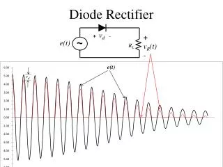
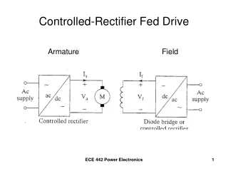
Controlled Rectifier Fed DC Drives • To obtain variable DC voltage from fixed AC source • DC current flows in only 1 direction • Example of a drive system EEEB443 - Control & Drives
Q1 Q2 Q3 Q4 T Controlled Rectifier Fed – Single-phase DC Drives • Two-quadrant drive • Limited to applications up to 15 kW • Regeneration (Q4) only be achieved with loads that can drive the motor in reverse (-ve) EEEB443 - Control & Drives
90o 180o ia + Va Single-phase supply Controlled Rectifier Fed – Single-phase DC Drives • Two-quadrant drive For continuous current: • Armature voltage where Vm = peak voltage • Armature current • Field voltage EEEB443 - Control & Drives
90o 180o ia + Va Single-phase supply Controlled Rectifier Fed – Single-phase DC Drives + Ea • Two-quadrant drive For Quadrant 1 operation: • positive Ea and Va positive • a 90 • Ia positive • Rectifier delivers power to motor, i.e. forward motoring. Q1 EEEB443 - Control & Drives
90o 180o ia Va + Single-phase supply Controlled Rectifier Fed – Single-phase DC Drives Ea + • Two-quadrant drive For Quadrant 4 operation: • negative Ea negative • a > 90 Va negative • Ia positive (still in same direction) • Rectifier takes power from motor, i.e. regenerative braking. Q4 EEEB443 - Control & Drives
+ Va Single-phase supply Single-phase supply Q1 Q2 Q3 Q4 T Controlled Rectifier Fed – Single-phase DC Drives • Four-quadrant drive • Converter 1 for operation in 1st and 4th quadrant • Converter 2 for operation in 2nd and 3rd quadrant • Limited to applications up to 15 kW ia Two rectifiers connected in anti-parallel across motor armature Converter 1 Converter 2 EEEB443 - Control & Drives
+ V1 Controlled Rectifier Fed – Single-phase DC Drives • Four-quadrant drive For continuous current: • Both converters are operated to produce the same dc voltage across the terminal, i.e.: where and (Vm = peak supply voltage) • Hence, firing angles of both converters must satisfy the following: • Armature current • Field voltage V2 + Converter 1 Converter 2 EEEB443 - Control & Drives
Q1 Q2 Q3 Q4 T Controlled Rectifier Fed – Three-phase DC Drives • Two-quadrant drive • Limited to applications up to 1500 kW • Regeneration (Q4) only be achieved with loads that can drive the motor in reverse (-ve) EEEB443 - Control & Drives
ia + Va 3-phase supply 90o 180o Controlled Rectifier Fed – Three-phase DC Drives • For continuous current: • Armature voltage where VL-L, m = peak line-to-line voltage • Armature current • Field voltage (assuming a three-phase supply is used for field excitation) EEEB443 - Control & Drives
Three-phase Controlled Rectifier 2Q DC Drive – Example EEEB443 - Control & Drives
+ Va 3-phase supply 3-phase supply Q1 Q2 Q3 Q4 T Controlled Rectifier Fed – Three-phase DC Drives • Four-quadrant drive • Converter 1 for operation in 1st and 4th quadrant • Converter 2 for operation in 2nd and 3rd quadrant Ia +ve, Va +ve or -ve Ia -ve, Va +ve or -ve Converter 1 Converter 2 ia Two rectifiers connected in anti-parallel across motor armature EEEB443 - Control & Drives
+ Va Q1 Q2 T Q3 Q4 Controlled Rectifier Fed – Three-phase DC Drives • Four-quadrant driveFor continuous current: where VL-L, m = peak line-to-line voltage. • Similar to single-phase drive: Converter 1 Converter 2 Converter 2: Ia -ve, Va +ve Converter 1: Ia +ve, Va +ve ia Converter 2: Ia -ve, Va -ve Converter 1: Ia +ve, Va -ve EEEB443 - Control & Drives
+ Va Controlled Rectifier Fed – Three-phase DC Drives • For continuous current: • Armature current • Field voltage • Disadvantages: • Circulating current • Inductors L1 and L2added to reduce circulating currents • Slow response L1 ia L2 Converter 1 Converter 2 EEEB443 - Control & Drives
Three-phase Controlled Rectifier 4Q DC Drive – Example EEEB443 - Control & Drives
R1 M1 3-phase supply Q1 Q2 + Va - Q3 Q4 T M2 R2 Controlled Rectifier Fed – Three-phase DC Drives • Four-quadrant drive • One controlled rectifier with 2 pairs of contactors • M1 and M2 closed for operation in 1st and 4th quadrant • R1 and R2 closed for operation in 2nd and 3rd quadrant ia ia EEEB443 - Control & Drives
Rectifier Fed DC Drives Problems • Distortion of Supply • Controlled rectifier introduces harmonics to supply currents and voltages which cause: • heating and torque pulsations in motor • resonance in power system network – interaction between rectifier RL with capacitor banks in system • Solution - eliminate most dominant harmonics by: • install LC filters at input of converters – tuned to absorb most dominant harmonics (i.e. 5th and 7th harmonics) • Use 12-pulse converter – consists of two 6-pulse controlled rectifiers connected in parallel • Selective switching of supply input using self-commutating devices (eg. GTOs, IGBTs) in the converter EEEB443 - Control & Drives
Rectifier Fed DC Drives Problems 12-pulse converter – consists of two 6-pulse controlled rectifiers connected in parallel EEEB443 - Control & Drives
Rectifier Fed DC Drives Problems • Low supply power factor • Power factor related to firing angle of rectifier • Low power factor especially during low speed operations • Solution: • Employ pulse-width modulated (PWM) rectifiers using GTOs, IGBTs • High power factor • Low harmonic supply currents • Low efficiency - high switching losses (disadvantage) EEEB443 - Control & Drives
Rectifier Fed DC Drives Problems • Effect on motor • Ripple in motor current – harmonics present (most dominant is 6th harmonic) • causes torque ripple, heating and derating of motor • solution: extra inductance added in series with La • Slow response • Discontinuous current may occur if • Lanot large enough • Motor is lightly loaded • Effect of discontinuous current • Rectifier output voltage increases motor speed increases (poor speed regulation under open-loop operation) EEEB443 - Control & Drives
References • Rashid, M.H, Power Electronics: Circuit, Devices and Applictions, 3rd ed., Pearson, New-Jersey, 2004. • Dubey, G.K., Fundamentals of Electric Drives, 2nd ed., Alpha Science Int. Ltd., UK, 2001. • Krishnan, R., Electric Motor Drives: Modeling, Analysis and Control, Prentice-Hall, New Jersey, 2001. • Nik Idris, N. R., Short Course Notes on Electrical Drives, UNITEN/UTM, 2008. • Ahmad Azli, N., Short Course Notes on Electrical Drives, UNITEN/UTM, 2008. EEEB443 - Control & Drives
Three-Phase Full-Converter Figure 10.5 Reference: Rashid, M.H, Power Electronics: Circuit, Devices and Applictions, 3rd ed., Pearson, New-Jersey, 2004 EEL 4242 by Dr. M.H. Rashid
Waveforms and Conduction Times Figure 10.5 Reference: Rashid, M.H, Power Electronics: Circuit, Devices and Applictions, 3rd ed., Pearson, New-Jersey, 2004 EEL 4242 by Dr. M.H. Rashid