Download
1 / 20
250 likes | 1.25k Views
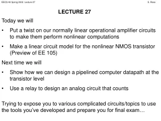
Good luck to Marquette in the NCAA Final Four!. Today we will Review NMOS and PMOS I-V characteristic Practice useful method for solving transistor circuits Build a familiar circuit element using a transistor. NMOS I-V CHARACTERISTIC. G. + V GS _. I G. I D. S. D.

E N D
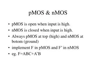
Good luck to Marquette in the NCAA Final Four! • Today we will • Review NMOS and PMOS I-V characteristic • Practice useful method for solving transistor circuits • Build a familiar circuit element using a transistor
NMOS I-V CHARACTERISTIC G + VGS _ IG ID S D - VDS + • Since the transistor is a 3-terminal device, there is no single I-V characteristic. • Note that because of the gate insulator, IG = 0 A. • We typically define the MOS I-V characteristic as • ID vs. VDS for a fixed VGS. • 3 modes of operation
NMOS I-V CHARACTERISTIC ID triode mode saturation mode VGS = 3 V VDS = VGS - VTH(N) VGS = 2 V VGS = 1 V VDS (VGS≤ VTH(N)) cutoff mode
NMOS I-V CHARACTERISTIC • Cutoff Mode • Occurs when VGS≤ VTH(N) • ID = 0 • Triode Mode • Occurs when VGS > VTH(N) and VDS < VGS - VTH(N) • Saturation Mode • Occurs when VGS > VTH(N) and VDS≥ VGS - VTH(N)
PMOS I-V CHARACTERISTIC G IG + VGS _ ID S D - VDS + Symbol has “dot” at gate. NMOS does not. ID, VGS, VDS, and VTH(P) are all negative for PMOS. These values are positiveforNMOS. Channel formed when VGS < VTH(P). Opposite for NMOS. Saturation occurs when VDS≤ VGS – VTH(P). Opposite for NMOS.
PMOS I-V CHARACTERISTIC (VGS≥ VTH(P)) cutoff mode VDS VGS = -1 V VGS = -2 V VDS = VGS - VTH(P) ID VGS = -3 V triode mode saturation mode
PMOS I-V CHARACTERISTIC • Cutoff Mode • Occurs when VGS ≥ VTH(P) • ID = 0 • Triode Mode • Occurs when VGS < VTH(P) and VDS > VGS - VTH(P) • Saturation Mode • Occurs when VGS < VTH(P) and VDS ≤ VGS - VTH(P)
SATURATION CURRENT Since l is small or zero, current ID is almost constant in saturation mode. We can call this current IDSAT:
LINEAR AND NONLINEAR ELEMENTS We need to find out how transistors behave as part of a circuit. • To solve a transistor circuit, obtain: • the nonlinear ID vs. VDS characteristic equation for the transistor • The linear relationship between ID vs. VDS as determined by the surrounding linear circuit Linear circuit G + VGS _ IG ID Then simultaneously solve these two equations for ID and VDS. S D - VDS +
SOLVING TRANSISTOR CIRCUITS: STEPS • Guess the mode of operation for the transistor. (We will learn how to make educated guesses). • Write the ID vs. VDS equation for this mode of operation. • Use KVL, KCL, etc. to come up with an equation relating ID and VDS based on the surrounding linear circuit. • Solve these equations for ID and VDS. • Check to see if the values for ID and VDS are possible for the mode you guessed for the transistor. If the values are possible for the mode guessed, stop, problem solved. If the values are impossible, go back to Step 1.
CHECKING THE ANSWERS • NMOS • VDS must be positive • ID must be positive • VDS < VGS – VT(N) in triode • VDS≥ VGS – VT(N) in saturation • VGS > VT(N) in triode or saturation • VGS ≤ VT(N) in cutoff • PMOS • VDS must be negative • ID must be negative • VDS> VGS – VT(P) in triode • VDS≤VGS – VT(P) in saturation • VGS< VT(P) in triode or saturation • VGS ≥ VT(P) in cutoff
1.5 kW D ID + VDS _ 4 V G + VGS _ 3 V + _ + _ S EXAMPLE • Guess the mode: • Since VGS > VTH(N), not in cutoff mode. Guess saturation mode. 2) Write transistor ID vs. VDS: • Write ID vs. VDS equation using KVL: VTH(N) = 1 V, ½ W/L mnCOX = 250 m A/V2, l = 0 V-1.
1.5 kW D ID + VDS _ 4 V G + VGS _ 3 V + _ + _ S EXAMPLE • Solve: • ID = 1mA VDS = 2.5 V • Check: • ID and VDS are correct sign, and VDS≥ VGS-VT(N) as required in saturation mode. VTH(N) = 1 V, ½ W/L mnCOX = 250 m A/V2, l = 0 V-1.
1.5 kW D ID + VDS _ 4 V G + VGS _ 3 V + _ + _ S WHAT IF WE GUESSED THE MODE WRONG? • Guess the mode: • Since VGS > VTH(N), not in cutoff mode. Guess triode mode. 2) Write transistor ID vs. VDS: ID = 2·250·10-6(3 – 1 – VDS/2)VDS • Write ID vs. VDS equation using KVL: VTH(N) = 1 V, ½ W/L mnCOX = 250 m A/V2, l = 0 V-1.
1.5 kW D ID + VDS _ 4 V G + VGS _ 3 V + _ + _ S WHAT IF WE GUESSED THE MODE WRONG? • Solve for VDS with quadratic • equation: • VDS = {4 V, 2.67 V} • 5) Check: • Neither value valid in triode mode! VDS > VGS – VT(N) not allowed in triode mode. VTH(N) = 1 V, ½ W/L mnCOX = 250 m A/V2, l = 0 V-1.
GUESSING RIGHT How do you guess the right mode? Often, the key is the value of VGS. (We can often find VGS directly without solving the whole circuit.) ID ID VGS= VT(N) + e VGS≤ VT(N) probably saturation definitely cutoff VDS VDS VGS- VT(N) = e
GUESSING RIGHT When VGS >> VTH(N), it’s harder to guess the mode. ID triode mode saturation mode VGS - VTH(N) If ID is small, probably triode mode VDS
+ _ + _ A CLOSER LOOK This circuit acts like a constant current source, as long as the transistor remains in saturation mode. IDSAT does not depend on the attached resistance if saturation is maintained. In this circuit, the transistor delivered a constant current IDSAT to the 1.5 kW resistor. 1.5 kW D ID + VDS _ 4 V G + VGS _ 1.5 kW IDSAT 3 V S
+ _ + _ A CLOSER LOOK • The circuit will go out of saturation mode if • VGS < VT(N) or • VDS < VGS – VT(N) • This can happen if VGS is too large or too small, or if the load resistance is too large. IDSAT does depend on VGS; one can adjust the current supplied by adjusting VGS. RL D ID + VDS _ VDD G + VGS _ RL IDSAT VGS S
+ _ ANOTHER EXAMPLE • Guess the mode: • What is VGS? • No current goes into/out gate. • VGS = 3 V by voltage division. • Guess saturation (randomly). 1.5 kW 2 kW D ID 4 V G + VDS _ 2) Write transistor ID vs. VDS: + VGS _ 6 kW S • Write ID vs. VDS equation using KVL: VTH(N) = 1 V, ½ W/L mnCOX = 250 m A/V2, l = 0 V-1. Effectively the same circuit as previous example: only 1 source.