Download
1 / 173
1.74k likes | 1.75k Views
Mr. Wen Chen<br>Overseas Marketing Manager<br>WCB BEARING CO.,LTD <br>Phone: 8617702586093 QQ: 2940894886 <br>Skype: youlite2016 Whatsapp: 8617702586093 <br>Wechat: 17702586093 <br>Email: wenchen@wcbearing.com <br>Website: http://www.wcbearing.com/<br>ADD: Yunlong District, XuZhou City, JiangSu Province, 221000, China

E N D
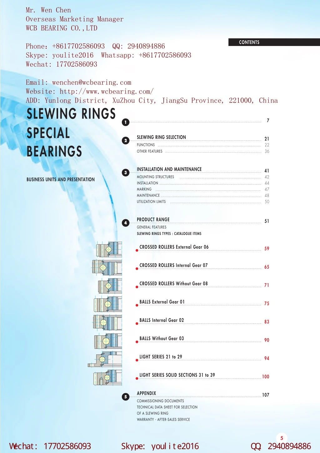
Mr. Wen Chen Overseas Marketing Manager WCB BEARING CO.,LTD CONTENTS Phone:+8617702586093 QQ: 2940894886 Skype: youlite2016 Whatsapp: +8617702586093 Wechat: 17702586093 Email: wenchen@wcbearing.com Website: http://www.wcbearing.com/ ADD: Yunlong District, XuZhou City, JiangSu Province, 221000, China SLEWING RINGS SPECIAL BEARINGS 7 1 SLEWING RING SELECTION 21 22 36 2 FUNCTIONS OTHER FEATURES INSTALLATION AND MAINTENANCE 41 42 44 47 48 50 3 MOUNTING STRUCTURES INSTALLATION MARKING MAINTENANCE UTILIZATION LIMITS BUSINESS UNITS AND PRESENTATION PRODUCT RANGE 51 4 GENERAL FEATURES SLEWING RINGS TYPES : CATALOGUE ITEMS CROSSED ROLLERS External Gear 06 59 CROSSED ROLLERS Internal Gear 07 65 CROSSED ROLLERS Without Gear 08 71 BALLS External Gear 01 75 BALLS Internal Gear 02 83 BALLS Without Gear 03 90 LIGHT SERIES 21 to 29 94 LIGHT SERIES SOLID SECTIONS 31 to 39 100 APPENDIX 107 5 COMMISSIONING DOCUMENTS TECHNICAL DATA SHEET FOR SELECTION OF A SLEWING RING WARRANTY - AFTER-SALES SERVICE 5 W echat: 17702586093 Skype: youl i te2016 Q Q : 2940894886 Province,China
w w w . w cbeari ng. com w enchen@ w cbeari ng. com W hatsapp: +8617702586093 BUSINESS UNITS AND PRESENTATION 1 • WIND TURBINE • GREEN INDUSTRY • SOLAR • HANDLING • MEDICAL • DEFENCE • PRECISION • TRANSPORT • PUBLIC WORKS • INDUSTRY • CRANES • PACKAGING • CONSTRUCTION • WATER TREATMENT • CAPABILITY • OFFSHORE • MINING 7 W echat: 17702586093 Skype: youl i te2016 Q Q : 2940894886
w w w . w cbeari ng. com w enchen@ w cbeari ng. com W hatsapp: +8617702586093 PRODUCT PRESENTATION BUSINESS UNIT WIND TURBINE 50% of the wind turbines in the world use WCB slewing rings for blade and yaw. Our design office is specialised to design specific bearings with 20 years life time. Our special sealing system gives completely tight bearings and we can propose integrated bearings with automatic lubrication system. Our finishing by grinding is the state of the art for the double row slewing rings. From 5kw up to 5 MW WCB supplies all the manufacturers in this field. SOLAR The rotation of the solar panels is a good solution to increase the production of energy. Because of our very compact design, WCB supplies the biggest solar farms in Europe. 8 W echat: 17702586093 Skype: youl i te2016 Q Q : 2940894886
w w w . w cbeari ng. com w enchen@ w cbeari ng. com W hatsapp: +8617702586093 PRODUCT PRESENTATION BUSINESS UNIT MEDICAL The WCB Medical slewing rings are characterised by a high rotating speed, constant rotating torque and low noise under rotation controlled in our anecoïd room. The perfect circle and the high precision of our bearing are the result of our specific finishing and the matching of the rings and the rolling elements. We propose also innovative sealing solutions to avoid any leakage in a clean environment. 1 PRECISION The success of the WCB slewing ring is the result of the precision of our finishing by grinding. All our production is perfectly under control and the matching of the rings and the rolling elements, gives batch after batch, the certainty to obtain the right bearing for this very demanding application. We propose also motor torque bearings. Our tailor made design follows perfectly the specific requirements of the customers. The most famous worldwide robots and machine tools manufacturers choose WCB all around the world. 9 W echat: 17702586093 Skype: youl i te2016 Q Q : 2940894886
w w w . w cbeari ng. com w enchen@ w cbeari ng. com W hatsapp: +8617702586093 PRODUCT PRESENTATION BUSINESS UNIT PUBLIC WORKS The WCB slewing ring, a very robust mechanical part, is particularly adapted to these applications. Our process control gives the customer a very simple solution to set up the pinion (see page 45) and to save production time. The most famous worldwide manufacturers choose WCB for our optimised design and the quality of our service. CRANES Because of the light structure of the crane, the WCB slewing ring is an essential and strategic part. Our design matches perfectly the life time required by the customer. The quality and the precision of our manufacturing is the key to ensure good running after many cranes dismantling. In this application the WCB slewing ring helps construct buildings everyday all around the world with total security. 10 W echat: 17702586093 Skype: youl i te2016 Q Q : 2940894886
w w w . w cbeari ng. com w enchen@ w cbeari ng. com W hatsapp: +8617702586093 PRODUCT PRESENTATION BUSINESS UNIT PACKAGING 1 Large diameters and thin sections are the main characteristics of this application. These particular bearings require strict process control. The WCB slewing rings are very well-known in the world to accept the highest rotating speed and to control the temperature during working 24 hours a day. Our quality gives a very low level of maintenance. The WCB slewing rings manufacture millions of bottles all around the world everyday. WATER TREATMENT Compared with standard bearings, the WCB slewing ring is a good solution to reduce the assembling time, to simplify the structure and to increase the capacity of the whole system. The high capacity of our gear is the result of our process control. Many towns around the world use our product every day to treat water. Our worldwide company structure gives strong support to customers and to end users. 11 W echat: 17702586093 Skype: youl i te2016 Q Q : 2940894886
w w w . w cbeari ng. com w enchen@ w cbeari ng. com W hatsapp: +8617702586093 PRODUCT PRESENTATION BUSINESS UNIT OFFSHORE High speeds, high loads and salty environment require strong and precise components. The WCB slewing rings is the perfect answer to the offshore industry. Our specific design satisfy the main manufacturers of onboard and harbour cranes, winches, davits and rubber tired gantry cranes as well as propellers. We propose innovative solutions of sealing to completely protect the bearings from the environment. WCB follows the international certification standards. MINING Stacker reclaimers, tunnel boring machines and excavators are very demanding applications. The high capacity of the WCB slewing rings is obtained by the control of the hardening process of the raceways and the gears. Our logistic department supplies our product everywhere in the world even large diameter slewing rings. 12 W echat: 17702586093 Skype: youl i te2016 Q Q : 2940894886
w w w . w cbeari ng. com w enchen@ w cbeari ng. com W hatsapp: +8617702586093 PRODUCT PRESENTATION BUSINESS UNIT GREEN INDUSTRY 1 Forest and de-barker machines require strong components. The most famous worldwide manufacturers choose WCB for our optimised design and the capacity of our slewing rings to work in a tough environment. Our finishing by grinding brings a valid pre-loading which is very important for the life time of the bearing and the comfort of the forest machine’s drivers. Our slewing rings accept the shocks and the high rotating speed of the de-barkers as well as the temperature of the coldest forests. HANDLING The stiffness of the WCB slewing ring is a perfect solution for this type of application. Our special design gives very compact bearings, which is essential for this product. Our process control gives the customer a very simple solution to set up the pinion (see page 45) in order to save time during the mounting of the machines. 13 W echat: 17702586093 Skype: youl i te2016 Q Q : 2940894886
w w w . w cbeari ng. com w enchen@ w cbeari ng. com W hatsapp: +8617702586093 PRODUCT PRESENTATION BUSINESS UNIT DEFENCE The WCB slewing ring has a strong reputation for civilian or military applications. We manufacture steel, aluminium and titanium bearings for the most demanding customers in the world. Our precision is obtained by a specific process of grinding. Our design office proposes specific solutions for all types of environments. Capacity, low torque, stiffness and high rotating speed are our main characteristics. TRANSPORT The WCB slewing ring permits the bogie orientation and the carriage articulation. The stress spectrum applied to these slewing rings is very specific. Our know-how answers perfectly the protection from contaminants (salt, sand, rain and mud). We can also integrate special braking devices. The WCB slewing rings transport millions of people all around the world with train, trams and metro. We also supply slewing rings for the rotation of the truck’s wheels. 14 W echat: 17702586093 Skype: youl i te2016 Q Q : 2940894886
w w w . w cbeari ng. com w enchen@ w cbeari ng. com W hatsapp: +8617702586093 PRODUCT PRESENTATION VARIOUS INDUSTRY 1 WCB supplies slewing rings for a wide range of applications throughout the industry. Our design office will assist you to select the most effective solution price and capacity-wise. Our staff and agents worldwide will process your enquiries and provide full support to meet your customer’s requirements. The loads and working conditions defined and gathered by the customer in the IT ETR 911 data sheet enables the WCB Engineering Department to select the most suitable product. 15 W echat: 17702586093 Skype: youl i te2016 Q Q : 2940894886
w w w . w cbeari ng. com w enchen@ w cbeari ng. com W hatsapp: +8617702586093 PRODUCT PRESENTATION CONSTRUCTION BASIC CONSTRUCTION External or internal gear Lubrication holes Special steel, one-piece rings with or without gear Filler plug Blind or through holes, untapped or tapped Raceways Specially designed profile seal Balls or rollers made of bearing steel 16 W echat: 17702586093 Skype: youl i te2016 Q Q : 2940894886
w w w . w cbeari ng. com w enchen@ w cbeari ng. com W hatsapp: +8617702586093 PRODUCT PRESENTATION CONSTRUCTION MATERIALS For the slewing ring manufacture, WCB selects the best material specifications to suit most foreseen usages. These materials are manufactured by approved steel works. Inspections are carried out at each significant step of manufacturing what makes it possible to warrant the quality of the products. Most of the time, we select high-grade Carbon steels which permit us to meet all operating requirements. Core hardening and tempering are carried out when the applied stresses dictate these processes. 1 Tensile strength MPa 1100 - 1000 - Core hardened D1 900 - D2 800 - D3 42CrMo4 core hardened 700 - N Z 42CrMo4 normalized Normalized XC45 + 600 - Normalized state Core hardened state STANDARD GRADES Code letter Z Improved XC 45 Code letter X Code letter D 42 Cr Mo 4 code letter N 17 W echat: 17702586093 Skype: youl i te2016 Q Q : 2940894886
w w w . w cbeari ng. com w enchen@ w cbeari ng. com W hatsapp: +8617702586093 PRODUCT PRESENTATION CONSTRUCTION MATERIALS COMPONENTS WCB selects rolling elements :balls and rollers with very specific characteristics. Their assembly requires particular caution. Any action of dismantling bearings or replacement of rolling elements is definitely inadvisable and cancels the WCB warranty. EQUIVALENT STANDARDS IN VARIOUS COUNTRIES : The following table shows our standard steels with the nearest equivalent foreign grades COUNTRIES STANDARD XC45 Code Z/X 42CrMo4 Code N/D GERMANY DIN Ck 45 42CrMo4 U K B.S. 080M46 708M40 U.S.A. AISI 16B45 4142 ITALY UNI C45 42CrMo4 JAPAN JIS S45C SNB7 SPAIN UNE C45K (F1140) 42CrMo4 (F8232) SWEDEN SSSTAHL 1672 2244 AUSTRALIA ASA AS 1442-1045 AS 1444-4140 OTHERS MATERIALS : Specific factors of some applications or functional requirements may result in the use of materials such as : • Stainless steel. • Structural hardening steels or alloys. • Special steels for hardening under controlled atmosphere. • Case or nitrided steel. • Special steels for very low temperature. • Aluminium-based alloys. • Titanium alloys. • Plastic, composite materials. 18 W echat: 17702586093 Skype: youl i te2016 Q Q : 2940894886
w w w . w cbeari ng. com w enchen@ w cbeari ng. com W hatsapp: +8617702586093 PRODUCT PRESENTATION CONSTRUCTION HEAT TREATMENTS The slewing ring transmits loads from a turning part towards the fixed part of a mechanism. The applied stresses of the rolling elements on the raceways are calculated according to the Hertz laws and the modern criteria of plasticity.WCB carries out localized hardening treatments which makes it possible to satisfy these criteria just as well in terms of surface pressure as well as subsurface fatigue. In all cases, induction or flame hardening permits us to achieve the necessary hardness patterns and a sufficient depth simultaneously. In process systematic inspections during production enable us to warrant the quality and the reliability of the slewing ring treatment, according to WCB specifications. According to the level of applied stresses and if geometry allows it, the same kind of hardening process may be applied on gear teeth. Our calculation models allow us to select the kind of treatment required. Other processes of local hardening may also be provided, for example : case hardening, nitriding, etc. 1 19 W echat: 17702586093 Skype: youl i te2016 Q Q : 2940894886
w w w . w cbeari ng. com w enchen@ w cbeari ng. com W hatsapp: +8617702586093 PRODUCT PRESENTATION CAPABILITY TEMPERATURE SPEED The normal working temperature of the slewing rings ranges from - 25 up to + 70˚ C. Lower or higher temperatures are possible but require special design provisions by our Engineering Department. The slewing rings can work whether by oscillating motion or continuous motion. It is necessary to check that the circumferential raceway speed remains within the acceptable limits of respective bearing's capacity. ROTATIONAL SPEED ENVIRONMENT RPM In case when the working environment is particularly aggressive : • sea atmosphere, • dusty or abrasive environment (sand, coal...), particular protection devices must be incorporated such as : • labyrinths, • shields, • oil-bath. Preventive maintenance operations will be increased to ensure normal operation. 500 Curve 1 Curve 2 Curve 3 Area 4 400 300 200 100 Dm 0 500 1000 1500 2000 2500 3000 BEARING TYPE Crossed rollers raceway LUBRICATION TYPE Standard grease LIMITED SPEED (n. Dm) 24 000 to 35 000 Curve 1 Balls type raceway Standard grease 40 000 to 65 000 Curve 2 SHOCKS, VIBRATIONS Balls type with cage Grease or oil 70 000 to 130 000 Curve 3 If the slewing rings are continously sollicited by shocks and/or vibrations, the customer must mention it in the specifications in order to design the right piece. Specific design Oil or special greases Consult us Area 4 In any case, it is essential to consult our Engineering Department with the precise operating conditions. 20 W echat: 17702586093 Skype: youl i te2016 Q Q : 2940894886
w w w . w cbeari ng. com w enchen@ w cbeari ng. com W hatsapp: +8617702586093 SLEWING RING SELECTION 2 • SLEWING RINGS FUNCTIONS • OTHER FEATURES 21 W echat: 17702586093 Skype: youl i te2016 Q Q : 2940894886
w w w . w cbeari ng. com w enchen@ w cbeari ng. com W hatsapp: +8617702586093 SLEWING RING SELECTION SLEWING RING FUNCTIONS LOADS SELECTION The slewing ring, being the link between a mobile element and a fixed base, must have the capacity to transmit the stresses of the mobile part towards the base. It is necessary to accurately define all the actual stresses applied so that a suitable slewing ring with adequate capacity can be selected. This should include the effects due to masses and inertias of the payloads and structures. It is necessary to distinguish the fixed loads and the variable loads as well as the effects due to dynamic loads, the latter constituting "fatigue" stresses. The direction of forces affecting the slewing ring must be well defined so that the active tilting moment can be established. We distinguish : • The AXIAL LOADS whose direction is parallel to the slewing ring rotation axis. The resultant of these loads is called FA. • The RADIAL LOADS contained in planes perpendicular to the rotation axis. The resultant of these loads is called FR. AXIAL LOADS RADIAL LOADS 22 W echat: 17702586093 Skype: youl i te2016 Q Q : 2940894886
w w w . w cbeari ng. com w enchen@ w cbeari ng. com W hatsapp: +8617702586093 SLEWING RING SELECTION SLEWING RING FUNCTIONS LOADS SELECTION CALCULATION OF THE EQUIVALENT LOAD For the calculation, the resultant of the radial loads FR is transposed into an equivalent axial load using a factor KR as follows : • TILTING MOMENTS (bending) : in planes parallel to the rotation axis. The resulting moment working in the plane containing the rotation axis is called MT. For light series and solid sections : KR = 3,225 2 The equivalent loads Feq can be obtained by the following formula : • SLEWING TORQUE CD controls the slewing ring rotation. • For the horizontally mounted slewing rings : vertical rotation axis : Feq = FA + KR . FR For standard slewing ring : if : FR < 0,25 FA if : 0,25 < FR < 1 FA if : FR > 1 FA KR = 0,5 • For the vertically mounted slewing rings : horizontal rotation axis : Feq = FA + 1,2 . KR . FR KR = 1,5 KR = 2,4 TILTING MOMENT 23 W echat: 17702586093 Skype: youl i te2016 Q Q : 2940894886
w w w . w cbeari ng. com w enchen@ w cbeari ng. com W hatsapp: +8617702586093 For WCB For the USER N° Affaire : Name : Date : Date : AC VI RC Signature : Visa : DESIGN DATA SHEET 1.1 COMPANY : Tel. : 1.2 Address : Fax : 1.3 Person in charge of the project : Fonction : 2.1 DESCRIPTION OF THE APPLICATION + sketch (to be attached with loads applied) 2.2 Machine / project reference : New project : Yes No 2.3 Slewing ring position : Horiz. Vert. Other Utilisation mode : Continu. Intermittent Other 3.1 LOADS ON THE BEARING (including structural loads) : Applied Suspended Static Dynamic 3.2 3.3 Nominal Maximum Test Nominal Maximum Test 3.4 Utilisation % Time 3.5 Axial kN 3.6 Radial kN 3.7 Moment kNm 3.8 Rotating ring : Ext Int Speed (RPM) 3.9 Load factors applied : Excluded Included Values : 3.10 Required life : 4.1 GEAR External Internal Without gear Geometry S.R. Pinion Loads S.R. Pinion 4.2 Required Module Tangentiel load (kN) 4.3 Number of teeth required Torque (kNm) 4.4 Addendum modif. factor 5.1 CRITICAL ITEMS Dimensions Others : 5.2 Classification Commission FEM LLOYDS API BV DNV Other 5.3 Specification relative to the application : SPECIFIC REQUIREMENTS OF THE APPLICATION 6.1 Environment : Operating temperature : 6.2 Vibrations, shocks loads : Storing temperature : 6.3 Acceleration : Deceleration : Inert. mom./Rotation axis : Varied : 7.1 QUANTITY Yearly requirements : Qty per delivery : 8.1 REQUIRED DELIVERY TIME : IT ETR 911 Document available at the Commercial Department W echat: 17702586093 Skype: youl i te2016 Q Q : 2940894886
w w w . w cbeari ng. com w enchen@ w cbeari ng. com W hatsapp: +8617702586093 SLEWING RING SELECTION SLEWING RING FUNCTIONS BEARING FUNCTION The knowledge of loads and working conditions is necessary to allow us to design and dimension the "BEARING" function of the slewing ring i.e : movement type, speed, accelerations, temperatures, environment, etc. THE USAGE FACTOR KU is defined according to the particular operating conditions : vibrations, shocks, occasional or accidental overloading, etc. If no other value is specified, then the nominal value is taken as 1. The transmission of loads from one raceway to another varies according to the nature of applied loads. In order to calculate the ideal dimensions of the raceway, we define the load equivalent to all external efforts in the most stressed areas. These loads are corrected by factors according to the application, the usage, etc. We distinguish between : - the application factor - the usage factor - the safety factor THE SAFETY FACTORKS is defined from standardized criteria for applications which must meet specific regulations such as : FEM, LLOYDS, API... This generally has the value 1, as the designer of the machine must include the regulation factors in the calculation of the loads applied on the bearing. KA KU KS THE APPLICATION FACTOR KA is a coefficient taking into account the application specificity in relation to the slewing ring element. This factor is established from WCB experience. It is defined in the table "APPLICATION FACTORS". 26 W echat: 17702586093 Skype: youl i te2016 Q Q : 2940894886
w w w . w cbeari ng. com w enchen@ w cbeari ng. com W hatsapp: +8617702586093 SLEWING RING SELECTION SLEWING RING FUNCTIONS BEARING FUNCTION APPLICATION FACTORS Applications factors KA Applications factors KA Average speed Rpm Average speed Rpm 2 MACHINES MACHINES Armament turret 1,5 1,5 Mobile telecospic crane 1 1,65 Bucket 1,5 1,65 Offshore crane 1 1,8 Cable shovel 2 1,65 Post jib crane 1 1,35 Compacter 2,5 1,80 Railway crane 1 1,50 Concrete mixer 5 2,40 Rapid rotation radar 5 2 Concrete pump 1,5 1,65 Rapid rotation scanner 3,5 1,65 Dragline 1,5 1,65 Robotics 3,5 1,65 Dock crane 1 1,65 Service deck crane 0,8 1,35 Fairlead 0,8 1,35 Settler (water and sewage treatment) 0,6 1,35 Fork-lift truck 1 1,35 Slow rotation radar 1 1,35 Fork-lift wheel 1,5 1,50 Slow rotation radiology 1 1,35 Grabbing crane 1,5 1,80 Tower crane, slewing jib type 1 1,65 Heavy winch 2 1,65 Tower crane, slewing tower type 1 1,80 Hydraulic lift platform 1 1,50 Track hook crane 1,5 1,80 Hydraulic shovel 2,5 2 Truck crane 1 1,50 Loading dock crane 1 1,65 Turntable 1 1,35 Merry-go-round 5 2,40 Vibrating compacter 2,5 2 Mine digging machinery 1,5 2 Welding positionner 0,8 1,35 Mobile fixed boom crane 1 1,5 Windturbine 0,8 1,65 Mobile grapple crane 1 1,80 These factors are determinated statistically and are based on a large number of observations for each type of application. The standard parameters retained are as follows : • Theoretical service life : 6000 hours. • Work under normal weather conditions. • Conventional application (and not specific). 27 W echat: 17702586093 Skype: youl i te2016 Q Q : 2940894886
w w w . w cbeari ng. com w enchen@ w cbeari ng. com W hatsapp: +8617702586093 SLEWING RING SELECTION SLEWING RING FUNCTIONS BEARING FUNCTION Selection of the ring according to capacity Service life Many external factors have a very important influence on the service life of the bearing. Among others, we can cite : • geometric quality of supports, • structure deformation under load, • climatic conditions and environment, • quality of operating maintenance • conditions of use : repeated exposures to shocks, vibrations or sudden or intermittent movements can considerably reduce the theoretical service life. The ring size is determined by plotting the representative point of loads onto this curve. This point, called "appli-cation point" has the following coordinates : • on the horizontal axis : Px = Feq . KA . KU . KS The load capacity of the slewing ring is calculated according to its performance in function of : • its geometric envelope, • the nature of the ring materials, • the heat treatment carried out, • the nature, the number and the dimension of the rolling elements, • the contact parameters of the rolling elements. •on the vertical axis : Py = MT . KA . KU . KS The curve of the maximum permissible capacity is drawn on a graph whose Ox axis bears the equivalent axial load and the Oy axis bears the tilting moment. To simplify it, it is represented by a straight line called the "LIMIT CURVE". MT Limit curve Py MT O Px Feq Limit curve Py O Px In any case, the application point P must be under the limit curve. Feq KT = OL / OP An estimate of the theoretical service life can be obtained by comparing the application point to the limit curve : the ratio OL/OP is called KT. 28 W echat: 17702586093 Skype: youl i te2016 Q Q : 2940894886
w w w . w cbeari ng. com w enchen@ w cbeari ng. com W hatsapp: +8617702586093 SLEWING RING SELECTION SLEWING RING FUNCTIONS BEARING FUNCTION Service Life SERVICE FACTOR D An estimate of the service life D can be obtained using the opposite graph : • The curve indicates the estimated service life (hours) directly from the KT value on the horizontal axis. 2 75 000 50 000 25 000 10 000 7 500 5 000 2 500 1 000 1 1,5 2 2,5 3 Rotational speed influence KV SPEED FACTOR 1,2 The service life D, estimated on the graph is only valid for the applications having a low rotational speed : 1 RPM. The value obtained must be multiplied by the speed factor KV indicated on the opposite graph when speeds differ from this. 1,0 0,8 0,6 0,4 0,2 RPM 2 4 6 8 10 12 14 D(n) = KV x D For applications having oscillating movements, the following formula applies : naverage = 0,60 x nreal 29 W echat: 17702586093 Skype: youl i te2016 Q Q : 2940894886
w w w . w cbeari ng. com w enchen@ w cbeari ng. com W hatsapp: +8617702586093 SLEWING RING SELECTION SLEWING RING FUNCTIONS FASTENING FUNCTION In order to transmit the loads previously defined, it is necessary to realize an adequate mechanical fastening of the bearing on the associated frames, thus forming rigid connection of the ring and its supports. While several fastening methods are feasible, the most efficient one remains the use of screws and nuts. Welding operations are absolutely prohibited. The slewing ring proper functioning and the application safety are dependent on the correct bolting definition and fastening method during installation, complying with our workmanship. BOLTS QUALITY The ISO 898-1 standards define the bolting grade adapted to structure assemblies such as slewing rings.WCB recommends the use of HIGH TENSILE bolts grade 10.9 and exceptionally grade 8.8 or 12.9 with rolled threads after heat treat. External hexagon head screws must be preferred to cap screws (internal hexagon) whenever possible.WCB recommendation : screws and nuts, with guaranted mechanical properties, matched, prelubricated so as to obtain a known and permanent screw/nut friction factor. The surface coating on the bolts must not generate any embrittlement. The nuts must be of a same or higher grade as the associated screw. For a screw diameter d, a nut height of 1.d is recommended. For rings in normalized steel Z or N, the use of hardened flat washers is required. Minimal properties should be : • a yield strength greater than or equal to 600 Mpa, • a diameter : DR = 2 d, • a thickness : h > 0,3 d Minimal mechanical characteristics (according to ISO) GRADE TENSILE (MPa) YIELD (MPa) FATIGUE (MPa) Exceptional 8.8 800 640 40 Recommended 10.9 1040 940 40 Exceptional 12.9 1220 1100 40 30 W echat: 17702586093 Skype: youl i te2016 Q Q : 2940894886
w w w . w cbeari ng. com w enchen@ w cbeari ng. com W hatsapp: +8617702586093 SLEWING RING SELECTION SLEWING RING FUNCTIONS FASTENING FUNCTION FA BOLTING CALCULATION The WCB calculation formulae take into account the current standards and regulations as well as the many research and experimental findings. These calculations are mainly inspired by the AFNOR FD E 25.030, the recommendation VDI 2230 (1988) and the standard API 2C (1995). SUPPORTED LOAD 2 Supported loads must be distinguished from hanging (suspended) loads acting in tension. Consult WCB, in the case of hanging (suspended) loads . HANGING LOAD Standard calculation hypotheses • Supported loads acting in compression. • Equispaced bolts ; i.e equally positioned on the pitch circles. • Steel rings and supports. • Supports complying with our instructions : thickness, stiffness, surface eveness (see chapter STRUCTURES page 42). • Rings bolted directly onto its supports. • In cases of heavy radial loads, we recommend to use pilots or to glue so that bolts will not be subjected to shear stresses. • The clamping length must be at least equal to five times the diameter : LK > 5.d. FA LK LK d 31 W echat: 17702586093 Skype: youl i te2016 Q Q : 2940894886
w w w . w cbeari ng. com w enchen@ w cbeari ng. com W hatsapp: +8617702586093 SLEWING RING SELECTION SLEWING RING FUNCTIONS FASTENING FUNCTIONS Calculation of the number of bolts When the ring has been previously selected according to its utilization and its load capacity, the bolting is then determined to correspond to the bearing capacity. The calculation of the minimum number of fasteners is carried out according to the following formula for the most unfavourable load case. In any case, a sufficient number of bolts ensuring an effective connection between ring and support frames must be kept, in order to avoid any ring deformation. where : N = Number of bolts theoretically necessary. 1,6 = Tightening factor (assembly error factor) for torque wrench Grade B according to FD E 25-030. Fk = Bolt stretch factor, see sketch. MT = Total tilting moment applied to the ring in kNm. FA = Axial load in kN. Df = Fastener pitch circle diameter in m. Ts = Tightening tension. d = Bolt diameter in mm. Ø m = Raceway mean diameter in m. Bolt stretch factor Fk This factor takes the assembly geometry into account. It is based on the bolt diameter and the ratio of clamping length to diameter. The best fastening is obtained with through-holes in the ring and the supports : by using screws and nuts, the clamping length is long, bolt stiffness is satisfactory and tension losses are minimised. In case of screw fastening into tapped holes, the setting depth must not be less than 1.25.d. N = 1,6 . FK ( 4 . MT - FA . Df ) Df ( Ts - Fpc ) Fpc = Loss of tension due to embedding in kN, see graph. Lk = Clamping length in mm. BOLT STRETCH FACTOR Fk d 33 30 27 24 22 20 16 14 12 2,75 2,50 2,25 2,00 1,75 1,50 1,25 Lk/d 1,00 2 3 4 5 6 7 8 32 W echat: 17702586093 Skype: youl i te2016 Q Q : 2940894886
w w w . w cbeari ng. com w enchen@ w cbeari ng. com W hatsapp: +8617702586093 SLEWING RING SELECTION SLEWING RING FUNCTIONS FASTENING FUNCTIONS Tightening tension : Ts Tightening tension of fastening bolts must be sufficient to warrant the absence of looseness which is essential to ensure the resistance of the assembly fatigue. diameter is sufficient compared to the dynamic stresses imposed when operating. Calculation of under head contact pressure : Usually, this calculation is not required when treated flat washers are used. It is however recommended when cap screws are used. (Chc). 2 Ts> (2,25)[(4.MT)-FA+80 N.d.10-3] N Ø m Calculation of the minimum fastener preload : It is useful to check that the standar-dized preload of the chosen bolt The standardized tightening tension at 80% of Re must be selected from the following table according to the chosen bolt diameter : bolting grade 10.9. We must have : FB max < P adm Ac with FB max = Ts + 0,13.FE Diameter (mm) 12 14 16 20 22 24 27 30 33 with FE = ( 1 ) [ ( 4.MT ) - FA] N Ø m Tension (kN) 56 77 106 166 208 239 315 385 480 and Ac = ( π ) ( dw 4 Loss of tension : During tightening and under external loads, peening of the surface roughness of the contact parts occurs, reducing the initial bolts elongation and thus producing a loss of tension, which 2 - Di 2 ) decreases the preload in the assembly. This loss of tension has been tabulated on the following graph which shows values in function of diameter d and the ratio Lk/d. dw d Di LOSS OF TENSION Fpc 8 Db 7 Allowable pressure : for steels N and Z 400 MPa 6 for steels D and X 620 MPa 5 d for steels type E36 270 MPa 4 33 30 27 24 22 20 16 14 12 IMPORTANT REMARK The use of elastic washers whatever the type or model is absolutely pro- hibited and will void all warranty. 3 2 1 Lk/d 2 4 6 8 10 33 W echat: 17702586093 Skype: youl i te2016 Q Q : 2940894886
w w w . w cbeari ng. com w enchen@ w cbeari ng. com W hatsapp: +8617702586093 SLEWING RING SELECTION SLEWING RING FUNCTIONS SLEWING FUNCTION WCB slewing rings generally incorporate a SLEWING mechanism to control rotation of the mobile part. This function can be achieved by various means : GEOMETRY Most of the WCB bearings have a gear improved by positive addendum modification which notably decreases pressures as well as by a truncation avoiding teeth root interference at the pinion. It is also essential to make a positive addendum modification on the pinion teeth, in order to avoid the geometric interference which appears under 18 teeth. Furthermore, the drive stresses induce shaft bending and gear deformation which are harmful to good meshing. To prevent these faults, we recommend profile corrections be carried out on the pinions : i.e.crowning and tip relief. Our Engineering Department will assist upon request. RESISTANCE Our rating graphs indicate the values of allowable maximum tangential force in fatigue T. The continuous operating capacity is obtained by the application of a suitable load moderating factor. gear drive (the most frequent case) 1 belt drive 2 T = 2 CD Dref Cd = Torque on gear Dref = Reference diameter Unless otherwise stated, the indicated values are valid for geared rings made of normalized steel XC45 : code Z. When these values are not sufficient, WCB can proceed with contour hardening which considerably improves the resistance to tooth root bending and the resistance to contact pressure. For very heavy loading conditions, WCB carries out complete hardening of the tooth and of its root in the wheel rim. When only a better wear resistance is required, surface hardening of tooth flanks only is possible. chain drive 3 direct drive 4 GEAR DRIVE Involute teeth, spur or helical are directly cut into the outer or inner ring (spur gear only). addendum modification PROFILE ADDENDUM MODIFICATIONS 2,0 1,8 1,6 1,4 1,2 1,0 0,8 0,6 0,4 0,2 0 0,2 0,4 0,6 0,8 upper limit SPECIAL CASES maximum Henriot recommended value BETTER BENDING STRENGTH Z1+Z2 BETTER DRIVE minimum value lower limit 20 40 60 80 100 120 140 160 180 34 W echat: 17702586093 Skype: youl i te2016 Q Q : 2940894886
w w w . w cbeari ng. com w enchen@ w cbeari ng. com W hatsapp: +8617702586093 SLEWING RING SELECTION SLEWING RING FUNCTIONS SLEWING FUNCTION GEAR QUALITY Unless stated otherwise, WCB manufactures slewing ring gears according to AFNOR or DIN standards which meet the following criteria : 2 WITHOUT SUPERFICIAL HEAT TREATMENT Maximum diameter all sizes Maximum module 25 DIN class AFNOR class Options 12 12 Module 45 with special tooling 10-11-12 11-10-9 all sizes 20 9-10 8-9 3100 22 Specific equipment necessary 7-8 7 2500 20 • made upon request When a higher gear quality such as grade 5 or 6 is needed, gear grinding becomes necessary (ask our Engineering department). SUPERFICIALLY HARDENED GEAR • Generally, by contour hardening to 55 HRc (± 5). • The gear classes stated above are offset and WCB can meet AFNOR or DIN standards for grades 11-12. IMPORTANT WCB considers that the relevant gear characterizing parameters for each quality class defined by AFNOR, DIN or ISO must be met. In case a customer does not require all of the parameters and needs to meet only one or two of them, WCB can achieve higher qualities. 35 W echat: 17702586093 Skype: youl i te2016 Q Q : 2940894886
w w w . w cbeari ng. com w enchen@ w cbeari ng. com W hatsapp: +8617702586093 SLEWING RING SELECTION OTHER FEATURES PRECISION - TOLERANCES Standard ring tolerances are generally defined according to ISO 286-1 and 2 standards. For applications requiring a higher precision level : robotics, radars, etc. a better grade is considered. The tole- rance values are then indicated on the bearing drawing. For bearings of large diameter with thin cross sections where radial stiffness is low, the tolerance values must be considered when bearing is assembled to its supports, these ensuring proper circularity. GEOMETRY The selected criteria are : • For the diameters : Js 13 • For the centerings Bores : H9 Shafts : f9 • For the overall height : ± 1 mm FASTENING The bolt circle diameters are machined to tolerance Js10 with a minimum of ± 0,2 mm. GENERAL TOLERANCES TABLE (ACCORDING TO ISO 286-2) Diameter (in mm) 180 250 250 315 315 400 400 500 500 630 630 800 800 1000 1000 1250 1250 1600 1600 2000 2000 2500 2500 3150 from to Pilot H9 (in μm) +115 + 130 +140 +155 +175 +200 +230 +260 +310 +370 +440 +540 Spigot f9 (in μm) - 50 - 165 - 56 - 185 - 62 - 202 - 68 - 223 - 76 - 251 - 80 - 280 - 86 - 316 - 98 - 358 - 110 - 420 - 120 - 490 - 130 - 570 - 145 - 685 Diameter Js10 (in μm) ± 92 ± 105 ± 115 ± 125 ± 140 ± 160 ± 180 ± 210 ± 250 ± 300 ± 350 ± 430 Diameter Js13 (in mm) ± 0,36 ± 0,405 ± 0,445 ± 0,485 ± 0,55 ± 0,625 ± 0,70 ± 0,825 ± 0,975 ± 1,15 ± 1,4 ± 1,65 GEAR The value of the total run-out is indicated in the drawing title block. The measurement and tolerance over K teeth are also indicated on the drawing. This dimension includes the contribution of the ring to the meshing backlash. BEARING • The AXIAL RUN-OUT of the supporting faces is measured using a dial gauge over one full revolution (see opposite sketch). X X 36 W echat: 17702586093 Skype: youl i te2016 Q Q : 2940894886
w w w . w cbeari ng. com w enchen@ w cbeari ng. com W hatsapp: +8617702586093 SLEWING RING SELECTION OTHER FEATURES PRECISION - TOLERANCES • THE RADIAL RUN-OUT of the spigots is also measured by rotation (following sketch). • THE DEFLECTION UNDER MASTER LOAD is measured as follows : One of the bearing ring is fastened to a rigid support and a master load F is applied axially on the other ring to a point closely located to the raceway. The deflection under load F is measured using a dial gauge whose base is attached to the other ring. The deflection under standard load of every slewing ring is measured at the factory. This value is compared to the allowable limits, and is registered. 2 Y Y These measurements are carried out by placing the magnetic base of a dial gauge on the fixed ring, while the filler is taken in contact with the element to be measured. The reading will be obtained during one rotation of the turning ring (value T.I.R). DEFLECTION UNDER MASTER LOAD Maximum value T.I.R. mm mm 0,80 0,70 0,60 Radial Run-out 0,50 Axial Run-out 0,40 0,30 F 0,20 0,10 Raceway mean Ø in mm 500 1000 1500 2000 2500 3000 37 W echat: 17702586093 Skype: youl i te2016 Q Q : 2940894886
w w w . w cbeari ng. com w enchen@ w cbeari ng. com W hatsapp: +8617702586093 SLEWING RING SELECTION OTHER FEATURES SLEWING TORQUE Calculation of the necessary torque to enable a rotation of the whole assembly takes into account : • loads on the machine, • rotating masses, • distance of these masses to the rotation axis, • speeds and accelerations, • resisting torques. Ca : ACCELERATION TORQUE The torque needed to accelerate the loads from the initial speed up to the final speed, during time (t) is defined by : Ca = π . n . I . 10-3 30 . t t = Acceleration time in sec. n = Speed variation in RPM (Final speed - Initial speed) I = Moment of inertia of the machine in Kg . m2 I = I1 + I2 + I3 + ..... In Two types of torques are distinguished : Start up slewing torque : Cd = Crv + Crc Acceleration slewing torque : Cg = Crv + Crc + Ca where I1 à In = moments of inertia of the moving loads with regard to the rotation axis expressed in Kg . m2. Crv = Friction torque of unloaded bearing Crc = Rotating torque due to loads Ca = Acceleration torque Generally we have : I1 = G1 x r 1 In = Gn x r n G1 to Gn = Mass of various rotating components expressed in Kg. r 1 to r n = Distances between the loads centre of gravity and the ring rotation axis expressed in meters. 2 Cd = Starting torque 2 All these torques are expressed in kNm. Crc : ROTATION TORQUE DUE TO LOADS The starting torque required takes into consideration loads on the bearing and friction of the components. Balls type slewing ring Crc = [ Ø m Note : The resisting torque depends on the support surface flatness and lubrication. 13,11 MT + 3 FA + 11,34 FR]Ø m . 10-3 Crossed rollers type slewing ring : Crc = [ Ø m 15,3 MT + 3,75 FA + 8,19 FR]Ø m . 10-3 MT = Resulting moment in kNm Ø m = Raceway mean Ø in meters FA = Axial load in kN FR = Radial load in kN 38 W echat: 17702586093 Skype: youl i te2016 Q Q : 2940894886
w w w . w cbeari ng. com w enchen@ w cbeari ng. com W hatsapp: +8617702586093 SLEWING RING SELECTION OTHER FEATURES SLEWING TORQUE The friction torque of standard slewing rings is defined in the following graph.WCB, upon request, can supply slewing rings with lower or higher torque values. LOADS APPLIED ON THE RING Axial FA : 68 kN + 5 kN = 73 kN Radial FR : 0,29 kN, negligible Moment MT : 5 kN x 1,5 m = 7,5 kNm 2 SLEWING TORQUE : Raceway mean Ø = 2 meters Crv : according to the graph : 1 kNm Unloaded friction torque resistance in kNm 2 Crc = [ 13,11 x 7,5 + (73 x 3) + (11,34 x 0)] 2.10-3 2 Standard slewing rings having 2 seals Crc = 0,536 kNm 1,5 Slewing torque at start up Cd = 1 + 0,536 = 1,536 kNm 1 Platform moment of inertia : MR2 = 6800 x 22 = 13600 Kg m2 2 2 Cube moment of inertia : Mr2 = 500 x 1,52 = 1125 Kg m2 0,5 Light series slewing rings with 2 seals Raceway mean Ø in m Total moment of inertia : 13600 + 1125 = 14725 Kg m2 0,5 1 1,5 2 2,5 3 Acceleration torque : n = 6 - 2 = 4 RPM Acceleration time : 20 sec Ca = 14725 x π x 4 10-3 = 0,3084 kNm 30 x 20 APPLICATION EXAMPLE Platform diameter : 4 m. Platform mass : 6800 kg Cube mass : 500 kg Ball type slewing ring raceway mean Ø : 2 m. Distance from the cube to the rotation axis : 1,5 m. Initial speed : 2 RPM Final speed : 6 RPM Acceleration time : 20 sec. Slewing torque during acceleration Cg = 1 + 0,536 + 0,3084 = 1,845 kNm 1,5 m 500 kg 6800 kg 39 W echat: 17702586093 Skype: youl i te2016 Q Q : 2940894886
w w w . w cbeari ng. com w enchen@ w cbeari ng. com W hatsapp: +8617702586093 SLEWING RING SELECTION OTHER FEATURES PROTECTION SEALS SHROUDS SURVEY WCB slewing rings are generally equipped with protecting seals on both sides of the raceway. These seals have the function of : • protecting raceways against small-sized contaminating agents, • retaining the lubricant in the raceway. For specific requirements, WCBdesigns suitable protective devices,such as : • standard and specific seals, • lip seals • combination of two or more seals. For severe application conditions and in order to limit the effects of aggressive agents such as : • swarf and metal chips • welding grains • abrasives • mud • sand • water and heavy sea splashes • cutting fluids... If, during regreasing, large grease discharges are noticed, it is advisable to check : • that seal is still correctly positioned, • that seal is not damaged (cut, torn, worn), • that seals are still capable for proper bearing operation. Therefore, this seal can either be reinstalled or replaced. WCB strongly recommends to install effective protective shields. Furthermore, during cleaning with solvents or pressurised water, it is advisable to avoid working in the protective device area. PROTECTIVE SURFACE COATING SEAL RANGE TABLE Operating conditions Ranges For particular applications, WCB suggests a protective surface treatment, such as : Zinc plating (+ chromate coating)Phosphate 1 coating 2 Chemical nickel plating 3 Paint 4 to 9 Miscellaneous treatments, for example, chrome plating, Schoop's metal spraying process, anodic oxidization, etc. 5 Consult us. 40 W echat: 17702586093 Skype: youl i te2016 Q Q : 2940894886
w w w . w cbeari ng. com w enchen@ w cbeari ng. com W hatsapp: +8617702586093 INSTALLATION AND MAINTENANCE 3 • MOUNTING STRUCTURES • INSTALLATION • MARKING • MAINTENANCE • UTILIZATION LIMITS 41 W echat: 17702586093 Skype: youl i te2016 Q Q : 2940894886
w w w . w cbeari ng. com w enchen@ w cbeari ng. com W hatsapp: +8617702586093 RING INSTALLATION STRUCTURES SUPPORT STRUCTURES CHASSIS DESIGN Raceway mean diameter (mm) Minimum thickness (mm) 500 750 1000 1250 1500 2000 2500 3000 The slewing ring has a moderate axial stiffness : the diameter is large compared to the cross section. It must be mounted on a machined supporting base, ensuring sufficient stiffness with regard to the loads to be transmitted. This makes it possible to ensure an even distribution of stresses and to avoid any deformation during operation, which would be harmful to the good working of the ring. 25 30 35 40 50 60 70 80 Therefore, it is necessary to use supporting bases with a minimum thickness not less than the values indicated in the table above. The width of the supporting surfaces is to be at least equal to that of the ring. We recommend structural reinforcements in a circular frame placed directly beneath the raceway. For better loading uniformity, thick circular frames are preferred to thin reinforcements with ribs. SHAPE TOLERANCES Shape defects of the supports lead to deformations of the raceway. This can cause tight spots or possible seizure and will reduce the bearing service life. The maximum flatness defects must not exceed the values of the opposite table. Raceway mean diameter (mm) Maximum tolerance Crossed Roller (mm) Maximum tolerance Balls (mm) 500 750 1000 1250 1500 2000 2500 3000 0,10 0,12 0,15 0,18 0,20 0,25 0,29 0,32 0,12 0,18 0,21 0,25 0,28 0,33 0,38 0,42 42 W echat: 17702586093 Skype: youl i te2016 Q Q : 2940894886
w w w . w cbeari ng. com w enchen@ w cbeari ng. com W hatsapp: +8617702586093 RING INSTALLATION STRUCTURES SUPPORT STRUCTURES LONG WAVES These maximum values are allowable for "long waves" in the circumferential direction. "Short waves" for example between two fastening holes, must not exceed 1/4 of the values in the opposite table. Waves in the radial direction (conicity) must be less than 0,05 mm / m of raceway mean Ø. δ 3 SHORT WAVES δ4 STIFFNESS TOLERANCES The stiffness of the supporting frames must be such that deflections do not exceed the values of the opposite table under maximum load. Raceway mean diameter (mm) Maximum deflection (mm) 500 750 1000 1250 1500 2000 2500 3000 0,25 0,30 0,35 0,45 0,55 0,65 0,80 1,00 PLASTIC CEMENTS Several products are possible depending on the dimensions and the amount of out of flatness to be compensated. Detailed instructions are available from our Sales Department. If the above tolerances could not be met, then Epoxy-type resins can be used instead of finish-machining of the surfaces. 43 W echat: 17702586093 Skype: youl i te2016 Q Q : 2940894886
w w w . w cbeari ng. com w enchen@ w cbeari ng. com W hatsapp: +8617702586093 RING INSTALLATION INSTALLATION TRANSPORT - HANDLING UNPACKING - PREPARATION INSTALLATION Our slewing rings are carefully packed in order to avoid any damage during transport. Transport and storage are to be carried out in horizontal position only ; transport in other positions requires special methods. As with any mechanical precision part, the rings must be handled with care avoiding any shocks, particularly along the radial axis. Handling should be carried out with suitable equipment for the weight of the part, which is indicated on the identification tag. When unwrapping the bearing : • Take care not to cut the protective seals when removing the packing paper. • Cut this paper, preferably on the external diameter, and not on the upper or lower faces. WHEN INSTALLING THE BEARING : Structure • Make sure that supporting structures comply with specifications (see chapter STRUCTURES). • Check for chips, weld seam particles, corrosion signs, etc. • Check the good mating of the rings on the supports. When degreasing the bearing : • Use a standard commercially available solvent. Chlorine containing solvents are prohibited. • Take care not to introduce any solvent under the seals or in the raceways. • Before fitting the grease nipples or junction pipes, remove the plastic caps or the Hc screws from the greasing holes. SPIGOTS When loads along the radial axis are important, especially when the bearing is placed vertically, it is then mandatory to use the centerings provided for that purpose. The intercalative structural adhesive type LOCTITE 586 provides a good means to limit the relative displace-ments between rings and supports. See our technical instructions IT ETR 521, available upon request. DELIVERY - STORAGE The packed rings have an anticorrosive surface protection allowing a 6-month-storage in a covered and temperate room. A suitable protection must be applied for longer storage. It is necessary to regrease after each 18-month-period (see paragraph MAINTENANCE - LUBRICATION). POSITIONING The hardening junction which is marked by a red line on the geared ring, and located at the filler plug on the other ring, must be placed at 90˚ to the main load axis or to the arm supporting the load (see chapter MARKING). 44 W echat: 17702586093 Skype: youl i te2016 Q Q : 2940894886
w w w . w cbeari ng. com w enchen@ w cbeari ng. com W hatsapp: +8617702586093 RING INSTALLATION INSTALLATION INSTALLATION Fastening WHEN INSTALLING THE PINION : pattern are absolutely prohibited and will void all warranty. • Install all fasteners and tighten lightly. • Then tighten to the specified value using a properly calibrated torque wrench ; hydraulic devices are advisable. • Use a "star shape" pattern when torquing which ensures a uniform tightening over the whole periphery. The tightening torque to be applied is defined in the following table for bolt grade 10.9 and a screw/nut friction factor of 0,12 according to VDI 2230. Gear • Check that fasteners are really of the recommended grade, e.g. marked 10.9 on the head and that threads are properly lubricated. • For bearings in normalized steel Z or N, the use of treated hardened flat washers is required as follows : • the yield strength is greater than or equal to 600 Mpa, • the diameter DR = 2 d, • the thickness h > 0,3 d. The elastic washers type Belleville, Grower or others of whatever type or • The pinion should be located approximately at 90° of the major loading axis. • Adjust the driving pinion to the maximum eccentric point of the ring gear, marked by a blue line. • At this stage, the backlash must be within the limits of the calculated values or minimum at 0,05 x module. • When several pinions are used, each one must be adjusted to the same conditions. • During tests, make sure that good alignment of the pinion and of the slewing ring axes permits a satisfactory contact across all the gear width. • Before running, lubricate the teeth of the slewing ring gear and of the pinion (see chapter MAINTENANCE). 3 TIGHTENING TORQUE 10 12 14 16 18 20 22 24 27 30 33 Diameter (mm) 69 117 185 280 390 560 750 960 1400 1900 2600 Torque (N.m) STAR-SHAPED TIGHTENING 1 Checking the gear backlash 8 12 backlash 4 5 9 11 3 2 6 10 7 45 W echat: 17702586093 Skype: youl i te2016 Q Q : 2940894886
w w w . w cbeari ng. com w enchen@ w cbeari ng. com W hatsapp: +8617702586093 RING INSTALLATION INSTALLATION INSTALLATION Tests - inspections After final tightening of all fasteners : • Rotate the ring for at least 3 turns. • Recheck the backlash value on the gear mesh over one full revolution. • Measure the total deflection under a known load. The checked points should be marked. It is advisable to register these values in a maintenance logbook specific to the machine, see our "COMMISSIONNING DOCUMENTS" ref. IT-DTR.19.005. DEFLECTION MEASUREMENT UNDER LOAD ON MOUNTED SLEWING RING Operating process : • Place a measuring device between the two rings as close as possible to the raceway on the main load axis : precision grade 0,1 mm minimum. • Calibrate to zero, under a known load. • Apply a measured load. • Read the deflection value at the point considered. • Repeat this measurement in the previously marked points. • Take into account the deflection of the support chassis and the fasteners elongation corresponding to the instrument position. Measuring device 46 W echat: 17702586093 Skype: youl i te2016 Q Q : 2940894886
w w w . w cbeari ng. com w enchen@ w cbeari ng. com W hatsapp: +8617702586093 RING INSTALLATION MARKING IDENTIFICATION TAG Each ring is individually identified by a metallic tag riveted close to the filler plug on the ungeared ring. MADE IN CHINA This tag states : • manufacturing date, • part number of the ring, • its serial number, • its weight in kilograms. 03/1996 GROUPE DEFONTAINE 3 0 6 1 1 1 6 0 0 Z Z 1 2 A 0 6 1 1 1 6 0 0 Z Z 1 2 A N° 1996 330 Kg INSTALLATION MARKS In order to permit the correct installation of the bearing, WCB slewing rings are marked as follows : Hardening junction : • Located on the filler plug for the ungeared ring. • Marked by a red line on the gear face for the geared ring. These areas must be placed as close as possible to the neutral axis of the loads : ideally at zero moment axis. Gear run-out : The maximum point of the gear run-out is marked by : • Two blue lines on the corresponding tips of the teeth, • a O stamped on the face opposite the mounting surface. The backlash of the driving pinion must be adjusted at this point. 47 W echat: 17702586093 Skype: youl i te2016 Q Q : 2940894886
w w w . w cbeari ng. com w enchen@ w cbeari ng. com W hatsapp: +8617702586093 RING INSTALLATION MAINTENANCE MAINTENANCE - LUBRICATION A suitable lubrication is essential for the longevity of the raceways and gears. The operating conditions such as loads, temperatures, speeds, vibrations, etc... determine the choice of lubricant. GREASING HOLES GREASE QUANTITY Raceway : The grease quantity is defined by the Engineering Department whenever a detailed bearing calculation is provided. Approximate practical formula to determine the minimum necessary quantity "Q" in cm3 : Q = 0,005/3 x D x H with : D = raceway mean Ø of the bearing in mm. H = overall height of the ring in mm. In all cases, a light extrusion of new grease must appear at the protection seal lips. Radially or facially located, depending on design, these holes are generally tapped M10 x pitch . 1.00 and closed by plastic caps or Hc screws. Remove these plugs before fitting the slewing ring with grease nipples or linked to a centralized lubrication system. Caution : the filler plug for the rolling elements has a blind tapped hole which is not a greasing hole. RACEWAY Unless otherwise specified, the slewing rings are delivered greased. Standard grease : ESSO BEACON EP 2 or equivalent. Main properties required for multi-purpose grease : As being a significant component of the bearing, grease will improve the bearing capabilities and longevity. REGREASING METHODS Whenever the application allows it, greasing must be carried out during rotation at slow speed, on two revolutions minimum, through all the greasing holes. Recommendations for bearing lubricant : • Lithium-base soap. • Minimum viscosity of the base : 150 mm2/sec. • Grade NLGI 2. • Anti-wear and extreme pressure additives. • Service temperature : – 30° C to + 120° C • 4 ball test : weld load : ASTM D 2596 (NT24) > 300 • Maximum NDM : for balls for rollers Gear : The grease must entirely cover the flanks of the pinion and of the ring gear whether applying by brush or spraying. GREASING FREQUENCY Raceway and gear. The greasing frequency varies according to utilization and environ-ment. We recommend regreasing every 150 hours in normal usage. This frequency is to be reduced to 50 hours when the conditions of application are severe or if the environment is dusty or wet. Greasing is required, before and after a long idle period. Regrease every 6 months, while rotating, during prolonged idle periods. SPECIFIC APPLICATIONS Upon request, the WCB Engineering Department will provide solutions for extreme conditions : temperature, speed, etc. See our data sheet IT ETR 551. 60 000 30 000 GEAR A protection against oxidation is applied. 48 W echat: 17702586093 Skype: youl i te2016 Q Q : 2940894886
w w w . w cbeari ng. com w enchen@ w cbeari ng. com W hatsapp: +8617702586093 RING INSTALLATION MAINTENANCE MAINTENANCE - LUBRICATION CORRESPONDENCE TABLE BEARING Aralub HLP2 Rhus L 474/2 Energrease LS - EP2 Grease LMX Epexa 2 / Epexelf 2 Beacon EP2 Mobilux EP2 Retina EP2 - Alvania EPLF2 Multis EP2 - Lical EP2 GREASE BRAND ARAL GEAR Aralub LFZ1 Berulit GA 400 Energol WRL/GR 154 GS According to our experience, the greases mentioned in the opposite table are compatible with each other and with the components of the bearings. It is possible to use other lubricants provided that you are sure of their compatibility with the WCB standard recommendation beforehand. Greases containing molybdenum disulphide MoS2 are strictly forbidden. MOTUL/BECHEM BP CASTROL Cardrexa DC1 Surret Fluid NX Mobilgear OGL 007 Malléus GL 205 Ceran AD Ceran AD+ ELF 3 ESSO MOBIL SHELL TOTAL FINA ELF This table is subject to change in accordance with the manufacturers'research works. PREVENTIVE MAINTENANCE PROTECTION SURVEY WCB recommends to retighten the fasteners after the first two to four months of utilization and then proceed to a systematic yearly check. If any bolt is found loose, a further in deep examination is essential. The necessary preservative measures must then be exercised. Some regulations impose the replace-ment of fasteners every seven years or every 14 000 working hours. In any case, refer to local rules and regulations enforced connected with the application. ORIENTATION SURVEY A visual examination makes it possible to ensure the integrity of the protective seals : During cleaning prior to regreasing of the gear : • Check carefully for any foreign body at the tooth root, ring and pinion. • Check the even load distribution of the pinion on the entire width of the ring gear and correct the alignment of the axes if needed. • Check the backlash value. • absence of excessive stretch or rips, • correct positioning, • wear of the friction lip. If necessary, replace the seal. After regreasing, wipe clean residue of old grease and check for pollutants such as sand, coal, metallic particles, etc. FASTENER SURVEY It is particularly important to check that the required preload level of the bolts is still maintained as the fasteners of the slewing rings are essentially working in fatigue. 49 W echat: 17702586093 Skype: youl i te2016 Q Q : 2940894886
w w w . w cbeari ng. com w enchen@ w cbeari ng. com W hatsapp: +8617702586093 RING INSTALLATION UTILIZATION LIMITS CHECKING THE DEFLECTION UNDER LOAD Wear is the difference : u = J1 – J0. • The bearing must be placed under survey when : u > J0. • Its replacement must be considered when : u > 1,5 J0. and it is required when : u > 2 J0. WCB delivers its bearings with a preload ensuring proper functioning and optimum safety. During the product life, the preload decreases resulting in a noticeable increase of deflection under load. The bearing must be replaced when the deflection becomes incompatible with the proper functioning of the machine and with the required safety conditions for the type of material used. In any case, refer to laws and regulations in force pertaining to the application in the concerned country. ROTATION SURVEY To quantify the wear factor, it is necessary to know the deflection under load. • In new condition : J0 • At time of survey : J1 These measurements are made under the same initial conditions after having checked the tightening of fasteners (see chapter INSTALLATION, Tests - Inspection, page 46). It is most advisable to register the measured values in the maintenance logbook specific to the machine. 50 W echat: 17702586093 Skype: youl i te2016 Q Q : 2940894886
w w w . w cbeari ng. com w enchen@ w cbeari ng. com W hatsapp: +8617702586093 RANGE OF PRODUCTS • CODING SYSTEM • BEARING FAMILIES • DRAWINGS • CAPACITY CURVES • BEARING REFERENCES 4 CROSSED ROLLERS External Gear 06 CROSSED ROLLERS Internal Gear 07 CROSSED ROLLERS Without Gear 08 BALLS External Gear 01 BALLS Internal Gear 02 BALLS Without Gear 03 LIGHT SERIES 21 to 29 LIGHT SERIES SOLID SECTIONS 31 to 39 51 W echat: 17702586093 Skype: youl i te2016 Q Q : 2940894886
w w w . w cbeari ng. com w enchen@ w cbeari ng. com W hatsapp: +8617702586093 RANGE OF PRODUCTS CODING SYSTEM WCB bearings are designated by a part reference including numbers and letters, according to the opposite codes. GEOMETRY METALLURGY 06 1116 00 Z Z 1 2 A 06 1116 00 Z Z 1 2 A Family 06 1116 00 Z Z 1 2 A Mean raceway ball/roller pitch Ø 06 1116 00 Z Z 1 2 A Variation N° in the family 06 1116 00 Z Z 1 2 A Material code letter ungeared ring 06 1116 00 Z Z 1 2 A Material code letter geared ring Material code : Z Improved XC45 (or similar) X XC45 core hardened N 42CrMo4 normalized D 42CrMo4 core hardened K aluminium alloys J other materials 06 1116 00 Z Z 1 2 A 0 Gear treatment : gear without heat treatment 1 gear with contour hardening on flanks and roots 2 gear flanks superficially hardened 3 other hardening treatments 06 1116 00 Z Z 1 2 A 0 Surface coating : oil storage protection 1 zinc or cadmium plated + chromate coating 2 phosphate coating 3 chemical nickel plating paint : 40 WCB standard primer 41 to 49 specific paint systems 4 5 9 to miscellaneous treatments (6 = anodic oxidization) 06 1116 00 Z Z 1 2 A Revision index : Project drawings : revisions according to numerical index from 1 to 9 Manufacturing drawings : first production = index A subsequent revisions = index B to Z 52 W echat: 17702586093 Skype: youl i te2016 Q Q : 2940894886
w w w . w cbeari ng. com w enchen@ w cbeari ng. com W hatsapp: +8617702586093 RANGE OF PRODUCTS BEARING FAMILIES CROSSED ROLLERS STANDARD BALLS STANDARD LIGHT SERIES III SOLID SECTIONS III GEAR Class V Class III & V Class I V Class I V Ext. Int. Without Normal clearance Reduced clearance Normal clearance Reduced clearance Single row Double row Single row Double row Precision Precision • 06 16 01 11 21 24 27 31 34 37 • 07 17 02 12 22 25 28 32 35 38 • 08 18 03 13 23 26 29 33 36 39 DEFINITION OF CLASSES Classes I, III and V define the amount of internal preload of the bearing. Class V corresponds to the maximal preload. This table shows the main families of WCB slewing rings. Slewing rings of specific types are listed in the document IT ETR 002. FAMILY 06 FAMILY 01 FAMILY 21 - 24 - 27 4 FAMILY 07 FAMILY 02 FAMILY 22 - 25 - 28 FAMILY 08 FAMILY 03 FAMILY 23 - 26 - 29 FAMILY 16 FAMILY 11 FAMILY 31 - 34 - 37 FAMILY 17 FAMILY 12 FAMILY 32 - 35 - 38 FAMILY 18 FAMILY 13 FAMILY 33 - 36 - 39 53 W echat: 17702586093 Skype: youl i te2016 Q Q : 2940894886
w w w . w cbeari ng. com w enchen@ w cbeari ng. com W hatsapp: +8617702586093 RANGE OF PRODUCTS DRAWINGS (Ø 1116) raceway mean diameter CROSS SECTION OF THE BEARING 06 1116 00 40 (holes) = Ø 1035 Ø 985 H 9 pilot Lubrication holes Ø 984 Ø 22 10 G (59) 114 + 1,00 94 G 78 90 Ø 22 40 (holes) = Ø 1198 Ø 1240 f 9 spigot Ø 1271 reference diameter Ø 1289.5 Each bearing is designated by a drawing reference, example : 06 1116 00. Fastening : the drawing indicates : • 40 : number of fastening holes, • "=" symbolizes equispaced holes, • "#" indicates non equispaced holes, • 1035 : bolt circle diameter. The raceway mean diameter of the bearing is given for information only. The gap diameters cannot be used as spigots, except when their dimensions are toleranced on the drawing. The drawing defines both principal and functional dimensions : spigots, bolt patterns and dimensions, overall height, reference diameter of the gear. The symbol "G" indicates the arrangement of the lubrication holes, the standard tapping is : M 10 x 1,00 except for the light series and the solid section light series : M 8 x 1,00. This document is not contractual, the latest issue of the drawing is available upon request. 54 W echat: 17702586093 Skype: youl i te2016 Q Q : 2940894886
w w w . w cbeari ng. com w enchen@ w cbeari ng. com W hatsapp: +8617702586093 RANGE OF PRODUCTS CAPACITY CURVES A rating graph illustrating the various load capacities is associated with each bearing reference. This "capacity curve" shows the same reference number as the bearing. The steel specification which is used is indicated by the code letter. CURVES OF BEARING 06 1116 00 Tilting moment kN.m Gear m z x.m Z0 Z1 1500 10 = = = = = 125 + 10.50 116.45 kN 155.30 kN 1350 1200 1050 900 4 750 600 450 300 150 kN 0 500 1000 1500 2000 2500 3000 3500 4000 4500 5000 Axial load This dotted line symbolizes the maximum dynamic capacity of the bearing. The functional point revised with the application and utilization factors must never exceed this limit under maximum loading. • The functional point revised by utilization factors must never exceed this limit in normal operation. m = module : 10 z = number of teeth : 125 x.m = addendum modification (radius) : + 10.50 Z0 = Z : material 0 : gear without treatment Z1 = Z : material 1 : gear without contour hardening. • The title block indicates the main characteristics of the gear : m, z, xm, and the ultimate resistance to fatigue bending stress according to the gear ring material and heat treatment indicated by a material code letter. This solid line represents a utilization limit curve for a minimum application factor of 1,25. This dot-dash line indicates the bolting limit capacity for a supported load using bolts grade 10.9. 55 W echat: 17702586093 Skype: youl i te2016 Q Q : 2940894886
w w w . w cbeari ng. com w enchen@ w cbeari ng. com W hatsapp: +8617702586093 RANGE OF PRODUCTS BEARING REFERENCES BEARINGS WITH EXTERNAL GEAR - Classification according to external diameter External diameter 244 318 379 403,5 440 529 535 589 654 689 700 774 816 863 886 979 1022 1094 1144 1218 1289,5 1358 1431 1476 1604 1605 1727 1836 1929 1975 2027 2140 2165 2267 2342 2390 2534 2695 2790 3116 3200 Internal diameter Number of teeth 120 104 92 88 95 103 65 116 80 112 114 94 132 142 108 94 125 134 111 119 125 133 177 144 157 131 214 112 135 245 142 131 269 139 290 130 138 335 151 152 318 Bearing reference 01 0181 02 01 0235 00 01 0289 06 06 0307 00 01 0342 00 01 0422 01 06 0400 00 06 0475 22 06 0508 00 01 0555 01 06 0574 09 01 0626 00 06 0675 00 01 0765 01 06 0734 00 06 0823 18 01 0880 00 01 0947 00 06 0980 09 01 1050 00 06 1116 00 01 1180 00 01 1295 01 06 1250 21 06 1390 03 01 1410 00 01 1595 00 06 1595 04 01 1712 00 01 1845 02 06 1790 09 01 1895 00 01 2040 03 06 2002 00 01 2202 00 01 2130 00 06 2242 00 01 2560 01 06 2500 01 06 2810 09 01 3031 00 STD = STANDARD SF = THIN SERIES STD STD STD STD STD STD STD STD STD STD STD STD STD STD STD STD STD STD STD STD STD STD SF STD STD STD SF STD STD SF STD STD SF STD SF STD STD SF STD STD SF Height Weight Module Page Quality 125 169 210 234 265 323 305 383 390 455 479 516 573 679 610 717 770 833 869 930 984 1045 1200 1084 1206 1270 1500 1433 1565 1750 1615 1720 1950 1815 2091 1950 2042 2425 2290 2600 2914 25 45 45 55 50 54 75 75 85 74 77 82 90 82 85 5 2 3 4 4,5 4,5 5 8 5 8 6 6 8 6 6 8 10 8 8 10 10 10 10 8 10 10 12 8 16 14 8 14 16 8 16 8 18 18 8 18 20 10 75 75 75 59 76 76 59 59 60 76 60 77 60 77 61 61 77 78 61 78 62 78 79 62 62 79 79 63 80 80 63 80 81 63 81 81 64 82 64 64 82 14 20 25 28 45 61 62 98 89 85 118 129 102 155 178 159 179 228 268 330 325 176 503 653 469 213 791 617 244 1004 953 278 1174 373 1111 1482 411 1895 2200 716 100 82 82 100 98 114 98 63 110 130 110 63 135 110 63 150 130 68 140 70 130 144 63 164 164 90 56 W echat: 17702586093 Skype: youl i te2016 Q Q : 2940894886