Download
1 / 52
520 likes | 708 Views
Fuel Cell Simulator System. Martin Ordonez, Master’s Candidate Supervisors: Dr. M. Tariq Iqbal Dr. John E. Quaicoe. Faculty of Engineering and Applied Science Memorial University of Newfoundland. Introduction. Fuel Cells (FC) Why FC Simulators?. Organization.

E N D
Fuel Cell Simulator System Martin Ordonez, Master’s Candidate Supervisors: Dr. M. Tariq Iqbal Dr. John E. Quaicoe Faculty of Engineering and Applied Science Memorial University of Newfoundland
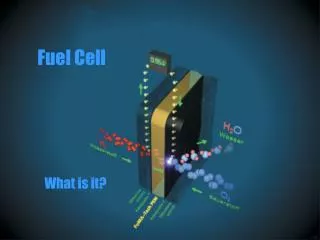
Introduction • Fuel Cells (FC) • Why FC Simulators?
Organization • Direct Methanol FC (DMFC) and Electronic Load Description • Dynamic Behavior of a DMFC • Fast Dynamic Power Converter for FC Simulators • Stand Alone FC Simulator • A Novel FC Simulator Based on a Small Single FC • Conclusions
DMFC System Description Membrane Electrode Assembly Cross section of the DMFC Anode and Cathode Plates
DMFC System Description Cross section of the DMFC Actual DMFC
Electronic Load for FC Systems Conceptual Schematic of the electronic load power stage and instrumentation Picture of the Electronic load
An Advanced Electronic Load for FC Systems DSP board top view Conceptual Schematic of the electronic load based on Digital Signal Processor (DSP) DSP board bottom view
An Advanced Electronic Load for FC Systems The advanced electronic load Power module expansion
DMFC Steady State Characteristic Curve FC Polarization Curve
Dynamic Behavior of a DMFC: Current Steps Response to a series of current steps : v-i plot Response to a series of current steps : time domain plot
Dynamic Behavior of a DMFC: Power Steps Response to a series of power steps : v-i plot Response to a series of power steps : time domain plot
Dynamic Behavior of a DMFC: Resistive Steps Response to a series of resistive steps : v-i plot Response to a series of resistive steps : time domain plot
Dynamic Behavior of a DMFC: Current Ripple DC+AC current test for 25Hz and 400Hz: v-i plot DC+AC current test for 25Hz and 400Hz: time domain plot
Current Ripple Operation: Output Power Reduction Power extraction as a percentage of the power extraction without ripple
Peak Power Availability Peak power extraction from no-load to 400mA : v-i plot Peak power extraction from no-load to 400mA : time domain plot
Summary • Advanced electronic load • Dynamic behavior of a DMFC • Power reduction with current ripple operation • Peak power availability • Examination of the generic FC dynamic model
Fast Dynamic Power Converter for FC Simulators • Dynamic response requirements? • Fast dynamic response • Large signal frequency response: • Unity Gain • Negligible phase shift DC+AC current test for 25Hz and 400Hz: v-i plot
Evaluation of Isolated Converters Following a reference signal Inductor and output current Flyback Forward Push pull, half and full bridge
Topology Selected for the Power Converter Reversible Buck converter • Advantages: • Avoid discontinuous conduction mode • Fast capacitor discharge (reverse current) • Best switch utilization • Suitable for switching surface control
Control Strategy: A Simple Analogy Which is the fastest way to travel by car? University Mall
Control Strategy: A Simple Analogy Answer: Time optimal Brake!!!! Maximum acceleration University Mall
Control Strategy: Facts About Switching Surfaces • Facts: • No unique SS can give a universal solution • Simple approach to predict the transient response: The closer the better
More Experimental Results Start up and resistive steps Frequency response
Summary • Analysis of the dynamic requirements • Converter topology selection • Control strategy: Selection of a SS • Prototype development • Experimental result
Stand Alone Fuel Cell Simulator • Suitable for Laboratory operation • No computer • No communication cards • No licensed software • Small low cost system Conceptual block diagram of the system
Parameters of the Model 1) 2) 3) 4)
DSP-based Implementation Flow diagram of the FC model and power converter controller
FC Stack Emulation: 55 Single Cells in Series Response to a series of current steps : v-i plot and time domain plot
Summary • Empirical model with reduced computational requirements • Development of a stand alone FC simulator based on a DSP • The most important feature: portability • Good match between the FC simulator and experimental results
A Novel FC Simulator Based on a Small Single FC • Replacing FC model for a small single FC • Include membrane drying, catalyst poisoning, aging, etc. • Avoid results that depart from reality • Use of scale up rules
A Novel FC Simulator Based on a Small Single FC • Control Area Network (CAN) bus • PC based monitoring and analysis • Fast dynamic power converter for FC simulators • Four modes of operation
A Novel FC Simulator Based on a Small Single FC • Control Area Network (CAN) bus • PC based monitoring and analysis • Fast dynamic power converter for FC simulators • Three modes of operation
A Novel FC Simulator Based on a Small Single FC • Control Area Network (CAN) bus • PC based monitoring and analysis • Fast dynamic power converter for FC simulators • Three modes of operation
A Novel FC Simulator Based on a Small Single FC • Control Area Network (CAN) bus • PC based monitoring and analysis • Fast dynamic power converter for FC simulators • Three modes of operation
Experimental Results: Current Ripple Operation 120 Hz current ripple operation: v-i plot and time domain plot Ch1: Power converter output voltage Ch2: Single FC output voltage Ch3: Single FC output current Ch4: Power converter output current
Experimental Results: Current Step Response Current step response : v-i plot and time domain plot Ch1: Power converter output voltage Ch2: Single FC output voltage Ch3: Single FC output current Ch4: Power converter output current
Concluding Summary • Electronic load development • Dynamic test of DMFC • Power converter design • Stand alone FC simulator • A novel FC simulator based on a single FC