Download

1 / 31
310 likes | 313 Views
Explore the role and applications of inductors in circuit design. Learn about inductance, self-inductance, and the behavior of inductors in RL circuits. Clear up misconceptions and gain a qualitative understanding of how inductors work.

E N D
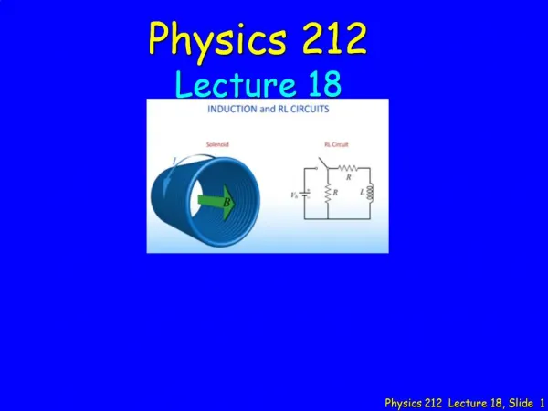
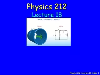
Physics 212 Lecture 18
Music • Who is the Artist? • Arturo Sandoval • Tiempo Libre • Chucho Valdes & Afro-Cuban Messengers • Freddie Omar con su banda • Los Hombres Calientes Legendary Cuban piano player Hadn’t been in the U.S. in many years Stop at Krannert in Fa10
OMG NO MORE MAGNETIC FIELDS. IM SOOOOOO HAPPY Your Comments What does an inductor actually do? What is it used for in circuit design? Could you show us an inductor in lecture? “glad this all makes sense before spring break...haha just kidding, im completely lost here.” I know that the time constant of the inductor is similar to that of the capacitor, but I don't really understand where the difference came from. “so if no current goes across the inductor to start, how does it have an emf? Also, how does an emf have a direction? Flux is a dot product with the B field and and area, and a change in a scalar (flux) over a change in another scalar (time) should give a scalar back right? am I missing something here or just over-thinking it?” Whats with all the (1/2)*x*y^2 equations? dont like it “The final checkpoint was confusing. Please go over how to determine current direction at different times of the switch being open or closed as well.” How can there be a current with no battery? Difficult checkpoints today! “I get most of this stuff, but I’m confused on the last checkpoint. Please go over it!” I don't really get why the voltage doubles when the switch is opened. I'd like some clarifications. Thanks! How can a neutral spiral of metal oppose the slowing down of charge flow. I still don't have a warm and fuzzy grasp of Faraday's law!!!! “Bringing back the circuits with switches makes me nervous.” “If you make this appear extremely intuitive in class, I will love you forever.” We’ll work on the qualitative picture of inductors in circuits How do you find the voltage across the inductor when there is no power source? Can we go over the entire last checkpoint “Explaining the intuition behind the solenoids and inductors would help a bunch for this lecture!” Checkpoint 2, what happens when the switch turns on right away to the current “I'm going to need some inDUCTance tape to keep all this info from falling out of my brain.” 05 I'm going to need some inDUCTance tape to keep all this info from falling out of my brain.
Some Exam Stuff • Exam THURSDAY (Mar. 29) at 7:00 • Covers material in Lectures 9 – 18 (through today’s lecture) • Bring your ID: Rooms determined by discussion section (see link) • Conflict exam at 5:15 – sign up in your gradebook before Fri. night (Mar. 16, 10:00 p.m.) • If you have conflicts with both of these, contact Prof. Park
dI dt Wrap a wire into a coil to make an “inductor”… e = -L From the prelecture: Self Inductance
dI dt eL= -L What this really means: emf induced across L tries to keep I constant L current I Inductors prevent discontinuous current changes ! It’s like inertia!
Checkpoint 1 Two solenoids are made with the same cross sectional area and total number of turns. Inductor B is twice as long as inductor A Compare the inductance of the two solenoids A) LA = 4 LBB) LA = 2 LBC) LA = LBD) LA = (1/2) LBE) LA = (1/4) LB “n halved and z doubled. Using the equation, L in case B is half of the L in case A.” “Both have same radius and both have 8 loops.” “B is twice as long so is twice as large ”
Checkpoint 1 2 (1/2)2 Two solenoids are made with the same cross sectional area and total number of turns. Inductor B is twice as long as inductor A Compare the inductance of the two solenoids A) LA = 4 LBB) LA = 2 LBC) LA = LBD) LA = (1/2) LBE) LA = (1/4) LB
WHAT ARE INDUCTORS AND CAPACITORS GOOD FOR? ” Can you have capacitors and inductors in the same circuit? “why inductors are important as opposed to capacitors. why use one instead of the other?” Inside your i-clicker
VL t = L/R I=V/R L R I VBATT t = L/R At t >> L/R: At t = 0: VL = 0 VR = VBATT I = VBATT/R (L is like a short circuit) I = 0 VL = VBATT VR = 0 (L is like a giant resistor) How to think about RL circuits Episode 1: When no current is flowing initially: I=0 L R VBATT
Checkpoint 2a In the circuit, the switch has been open for a long time, and the current is zero everywhere. At time t=0 the switch is closed. What is the current I through the vertical resistor immediately after the switch is closed? (+ is in the direction of the arrow) A) I = V/RB) I = V/2RC) I = 0 D) I = -V/2RE) I = -V/R “V_L == V, so applying KVL to the right loop, I == V/R.” “At t=0, no current flows through the inductor. The two resistors are in series. Hence, the overall resistance = 2R. Therefore, I = V/ 2R.” “the current runs through the solenoid, not the resistor.”
Checkpoint 2a I IL=0 I After: IL = 0 I = + V/2R In the circuit, the switch has been open for a long time, and the current is zero everywhere. At time t=0 the switch is closed. What is the current I through the vertical resistor immediately after the switch is closed? (+ is in the direction of the arrow) A) I = V/RB) I = V/2RC) I = 0 D) I = -V/2RE) I = -V/R Before: IL = 0
RL Circuit (Long Time) - + + - KVR:VL + IR = 0 What is the current I through the vertical resistor after the switch has been closed for a long time? (+ is in the direction of the arrow) A) I = V/RB) I = V/2RC) I = 0 D) I = -V/2RE) I = -V/R After a long time in any static circuit: VL = 0
VL t = L/R I=0 L R t = L/R At t >> L/R: At t = 0: I = 0 VL = 0 VR = 0 I = VBATT/R VR = IR VL = VR How to think about RL circuits Episode 2: When steady current is flowing initially: VBATT L R R I=V/R DEMO
Checkpoint 2b After a long time, the switch is opened, abruptly disconnecting the battery from the circuit. What is the current I through the vertical resistor immediately after the switch is opened? (+ is in the direction of the arrow) A) I = V/RB) I = V/2RC) I = 0 D) I = -V/2RE) I = -V/R “After the battery is disconnected, there will be a current of V/R because the inductor will have the initial voltage of the battery.” “It dissapates from the inductor through the resistor” “After long time V across solenoid is zero. Zero voltage zero current”
Checkpoint 2b circuit when switch opened L R IL=V/R After a long time, the switch is opened, abruptly disconnecting the battery from the circuit. What is the current I through the vertical resistor immediately after the switch is opened? (+ is in the direction of the arrow) A) I = V/RB) I = V/2RC) I = 0 D) I = -V/2RE) I = -V/R Current through inductor cannot change DISCONTINUOUSLY
+ - dI dt VL t = L/R V = IR + V = L - t = L/R where Why is there exponential behavior ? I L R
I L R Did we mess up?? VBATT VL t = L/R Lecture: Prelecture: No: The resistance is simply twice as big in one case.
Checkpoint 3a After long time at 0, moved to 1 After long time at 0, moved to 2 “Time constant is L/R, so the lower the resistance, the larger the time constant.” • After switch moved, which case has larger time constant? • Case 1 • Case 2 • The same “more resistors to run into in case 2” “The time it takes to get to switch one should be the same to get to switch #2”
Checkpoint 3a After long time at 0, moved to 1 After long time at 0, moved to 2 • After switch moved, which case has larger time constant? • Case 1 • Case 2 • The same
Checkpoint 3b After long time at 0, moved to 1 After long time at 0, moved to 2 • Immediately after switch moved, in which case is the voltage across the inductor larger? • Case 1 • Case 2 • The same “It has less resistance to decrease the initial voltage from the battery.” “More resistance v=IR. R larger so V is larger.” “full battery voltage appears across the inductors”
Checkpoint 3b Before switch moved: After long time at 0, moved to 1 After long time at 0, moved to 2 • Immediately after switch moved, in which case is the voltage across the inductor larger? • Case 1 • Case 2 • The same After switch moved:
Checkpoint 3c After long time at 0, moved to 1 After long time at 0, moved to 2 • After switch moved for finite time, in which case is the current through the inductor larger? • Case 1 • Case 2 • The same “Greater time constant means that the current will decay more slowly in case 1.” “The resistance allows the curent to last for longer.” “The currents are 0.”
Checkpoint 3c Immediately after: After long time at 0, moved to 1 After long time at 0, moved to 2 • After switch moved for finite time, in which case is the current through the inductor larger? • Case 1 • Case 2 • The same After awhile
Calculation The switch in the circuit shown has been open for a long time. At t = 0, the switch is closed. What is dIL/dt, the time rate of change of the current through the inductor immediately after switch is closed R1 R2 V L R3 • Conceptual Analysis • Once switch is closed, currents will flow through this 2-loop circuit. • KVR and KCR can be used to determine currents as a function of time. • Strategic Analysis • Determine currents immediately after switch is closed. • Determine voltage across inductor immediately after switch is closed. • Determine dIL/dt immediately after switch is closed.
Calculation IL = 0 What is IL, the current in the inductor, immediately after the switch is closed? • IL =V/R1 up(B) IL =V/R1 down (C) IL = 0 Current through inductor immediately AFTER switch is closed IS THE SAME AS the current through inductor immediately BEFORE switch is closed Immediately before switch is closed: IL = 0 since no battery in loop The switch in the circuit shown has been open for a long time. At t = 0, the switch is closed. R1 R2 V L R3 INDUCTORS: Current cannot change discontinuously !
Calculation R1 R2 I Immediately after switch is closed, circuit looks like: V R3 The switch in the circuit shown has been open for a long time. At t = 0, the switch is closed. R1 R2 V L R3 IL(t=0+) = 0 What is the magnitude of I2, the current in R2, immediately after the switch is closed? • (B) (C) (D) We know IL = 0 immediately after switch is closed
Calculation What is the magnitude of VL, the voltage across the inductor, immediately after the switch is closed? • (B) (C) (D) (E) I2 The switch in the circuit shown has been open for a long time. At t = 0, the switch is closed. R1 R2 V L R3 I2(t=0+) = V/(R1+R2+R3) IL(t=0+) = 0 Kirchhoff’s Voltage Law, VL-I2 R2 -I2 R3 =0 VL = I2 (R2+R3)
Calculation The switch in the circuit shown has been open for a long time. At t = 0, the switch is closed. What is dIL/dt, the time rate of change of the current through the inductor immediately after switch is closed R1 R2 V L R3 VL(t=0+) = V(R2+R3)/(R1+R2+R3) • (B) (C) (D) The time rate of change of current through the inductor (dIL /dt) = VL /L
Follow Up The switch in the circuit shown has been closed for a long time. What is I2, the current through R2 ? (Positive values indicate current flows to the right) R1 R2 V L R3 • (B) (C) (D) After a long time, dI/dt = 0 Therefore, the voltage across L = 0 Therefore the voltage across R2 + R3 = 0 Therefore the current through R2 + R3 must be zero !!
Follow Up 2 I2 • (B) (C) (D) (E) The switch in the circuit shown has been closed for a long time at which point, the switch is opened. What is I2, the current through R2 immediately after switch is opened ? (Positive values indicate current flows to the right) R1 R2 IL V L R3 Current through inductor immediately AFTER switch is opened IS THE SAME AS the current through inductor immediately BEFORE switch is opened Immediately BEFOREswitch is opened: IL = V/R1 ImmediatelyAFTERswitch is opened: IL flows in right loop Therefore, IL = -V/R1