Download
1 / 49
490 likes | 715 Views
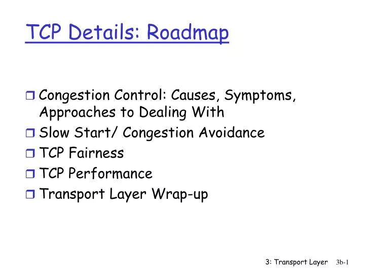
TCP Details: Roadmap. Congestion Control: Causes, Symptoms, Approaches to Dealing With Slow Start/ Congestion Avoidance TCP Fairness TCP Performance Transport Layer Wrap-up. Congestion: informally: “too many sources sending too much data too fast for network to handle”

E N D
TCP Details: Roadmap • Congestion Control: Causes, Symptoms, Approaches to Dealing With • Slow Start/ Congestion Avoidance • TCP Fairness • TCP Performance • Transport Layer Wrap-up 3: Transport Layer
Congestion: informally: “too many sources sending too much data too fast for network to handle” different from flow control! a top-10 problem! Principles of Congestion Control 3: Transport Layer
Congestion Signals • Lost packets:If there are more packets than resources (ex. Buffer space) along some path, then no choice but to drop some • Delayed packets: Router queues get full and packets wait longer for service • Explicit notification: Routers can alter packet headers to notify end hosts 3: Transport Layer
Congestion Collapse • As number of packets entering network increases, number of packets arriving at destination increases but only up to a point • Packet dropped in network => all the resources it used along the way are wasted => no forward progress • Internet 1987 3: Transport Layer
Congestion Prevention? • In a connection-oriented network: • Prevent congestion by requiring resources to be reserved in advance • In a connectionless network: • No prevention for congestion, just reaction to congestion (congestion control) 3: Transport Layer
two senders, two receivers one router, infinite buffers no retransmission large delays when congested maximum achievable throughput Causes/costs of congestion: scenario 1 3: Transport Layer
one router, finite buffers sender retransmission of lost packet Causes/costs of congestion: scenario 2 3: Transport Layer
(goodput) “perfect” retransmission only when loss: retransmission of delayed (not lost) packet makes larger (than perfect case) for same l l l > = l l l in in in out out out Causes/costs of congestion: scenario 2 “costs” of congestion: • more work (retrans) for given “goodput” • unneeded retransmissions: link carries multiple copies of pkt 3: Transport Layer
four senders multihop paths timeout/retransmit l l in in Causes/costs of congestion: scenario 3 Q:what happens as and increase ? 3: Transport Layer
Causes/costs of congestion: scenario 3 Another “cost” of congestion: • when packet dropped, any “upstream transmission capacity used for that packet was wasted! 3: Transport Layer
End-end congestion control: no explicit feedback from network congestion inferred from end-system observed loss, delay approach taken by TCP Network-assisted congestion control: routers provide feedback to end systems single bit indicating congestion (SNA, DECbit, TCP/IP ECN, ATM) explicit rate sender should send at Approaches towards congestion control Two broad approaches towards congestion control: 3: Transport Layer
Window Size Revised • Limit window size by both receiver advertised window *and* a “congestion window” • MaxWindow < = minimum (ReceiverAdvertised Window, Congestion Window) • EffectiveWindow = Max Window - (Last ByteSent - LastByteAcked) 3: Transport Layer
end-end control (no network assistance) transmission rate limited by congestion window size, Congwin, over segments: TCP Congestion Control Congwin 3: Transport Layer
Source Destination … Original: With Just Flow Control 3: Transport Layer
TCP Congestion Control: Two Phases • two “phases” • slow start • congestion avoidance • important variables: • Congwin: current congestion window • Threshold: defines threshold between two slow start phase, congestion control phase 3: Transport Layer
Don’t just send the entire receiver’s advertised window worth of data right away Start with a congestion window of 1 or 2 packets Slow start: For each ack received, double window up until a threshold, then just increase by 1 Congestion Avoidance: For each timeout, start back at 1 and halve the upper threshold “probing” for usable bandwidth: ideally: transmit as fast as possible (Congwin as large as possible) without loss increaseCongwin until loss (congestion) loss: decreaseCongwin, then begin probing (increasing) again TCP congestion control: 3: Transport Layer
Source Destination … “Slow” Start:Multiplicative Increase Multiplicative Increase Up to the Threshold “Slower” than full receiver’s advertised window Faster than additive increase 3: Transport Layer
Source Destination … TCP Congestion Avoidance: Additive Increase Additive Increase Past the Threshhold 3: Transport Layer
TCP Congestion Avoidance: Multiplicative Decrease too Congestion avoidance /* slowstart is over */ /* Congwin > threshold */ Until (loss event) { every w segments ACKed: Congwin++ } threshold = Congwin/2 Congwin = 1 perform slowstart 1 1: TCP Reno skips slowstart (fast recovery) after three duplicate ACKs 3: Transport Layer
Fast Retransmit • Interpret 3 duplicate acks as an early warning of loss (other causes? Reordering or duplication in network) • As if timeout - Retransmit packet and set the slow-start threshold to half the amount of unacked data • Unlike timeout - set congestion window to the threshhold (not back to 1 like normal slow start) 3: Transport Layer
Fast Recovery • After a fast retransmit, do congestion avoidance but not slow start. • After third dup ack received: • threshold = ½ (congestion window) • Congestion window = threshold + 2* MSS • If more dup acks arrive: • congestion Window += MSS • When ack arrives for new data,deflate congestion window: • congestionWindow = threshold 3: Transport Layer
blue line = value of congestion window in KB Short hash marks = segment transmission Long hash lines = time when a packet eventually retransmitted was first transmitted Dot at top of graph = timeout 0-0.4 Slow start; 2.0 timeout, start back at 1; 2.0-4.0 linear increase Connection Timeline 3: Transport Layer
Fairness goal: if N TCP sessions share same bottleneck link, each should get 1/N of link capacity TCP congestion avoidance: AIMD:additive increase, multiplicative decrease increase window by 1 per RTT decrease window by factor of 2 on loss event TCP Fairness AIMD TCP connection 1 bottleneck router capacity R TCP connection 2 3: Transport Layer
Two competing sessions: Additive increase gives slope of 1, as throughout increases multiplicative decrease decreases throughput proportionally Why is TCP fair? equal bandwidth share R loss: decrease window by factor of 2 congestion avoidance: additive increase Connection 2 throughput loss: decrease window by factor of 2 congestion avoidance: additive increase Connection 1 throughput R 3: Transport Layer
TCP Congestion Control History • Before 1988, only flow control! • TCP Tahoe 1988 • Congestion control with multiplicative decrease on timeout • TCP Reno 1990 • Add fast recovery and delayed acknowledgements • TCP Vegas ? • Tries to use space in router’s queues fairly not just divide BW fairly 3: Transport Layer
TCP Vegas • Tries to use constant space in the router buffers • Compares each round trip time to the minimum round trip time it has seen to infer time spent in queuing delays • Vegas in not a recommended version of TCP • Minimum time may never happen • Can’t compete with Tahoe or Reno 3: Transport Layer
Q:How long does it take to receive an object from a Web server after sending a request? TCP connection establishment data transfer delay Slow start A:That is a natural question, but not very easy to answer. Depends on round trip time, bandwidth, window size (dynamic changes to it) TCP latency modeling 3: Transport Layer
Notation, assumptions: O: object size (bits) Assume one link between client and server of rate R Assume: fixed congestion window, W segments S: MSS (bits) no retransmissions (no loss, no corruption) TCP latency modeling Two cases to consider: • Slow Sender (Big Window): Still sending when ACK returns • time to send window > time to get first ack • W*S/R > RTT + S/R • Fast Sender (Small Window):Wait for ACK to send more data • time to send window < time to get first ack • W*S/R < RTT + S/R 3: Transport Layer
TCP latency Modeling Number of windows: K := O/WS Fast Sender (Small Window): latency = 2RTT + O/R + (K-1)[S/R + RTT - WS/R] Slow Sender (Big Window): latency = 2RTT + O/R (S/R + RTT) – (WS/R) = Time Till Ack Arrives – Time to Transmit Window 3: Transport Layer
TCP Latency Modeling: Slow Start • Now suppose window grows according to slow start (not slow start + congestion avoidance). • Will show that the latency of one object of size O is: where P is the number of times TCP stalls at server waiting for Ack to arrive and open the window: - Q is the number of times the server would stall if the object were of infinite size - maybe 0. - K is the number of windows that cover the object. • S/R is time to transmit one segment • - RTT+ S/R is time to get ACK of one segment 3: Transport Layer
TCP Latency Modeling: Slow Start (cont.) Example: O/S = 15 segments K = 4 windows Q = 2 P = min{K-1,Q} = 2 Server stalls P=2 times. Stall 1 Stall 2 3: Transport Layer
TCP Latency Modeling: Slow Start (cont.) 3: Transport Layer
TCP Performance Limits • Can’t go faster than speed of slowest link between sender and receiver • Can’t go faster than receiverAdvertisedWindow/RoundTripTime • Can’t go faster than 2*RTT • Can’t go faster than memory bandwidth (lost of memory copies in the kernel) 3: Transport Layer
Experiment: Compare TCP and UDP performance • Use ttcp (or pcattcp) to compare effective BW when transmitting the same size data over TCP and UDP • UDP not limited by overheads from connection setup or flow control or congestion control • Use Ethereal to trace both 3: Transport Layer
TCP vs UDP What would happen if UDP used more than TCP? 3: Transport Layer
principles behind transport layer services: multiplexing/demultiplexing reliable data transfer flow control congestion control instantiation and implementation in the Internet UDP TCP Next: leaving the network “edge” (application transport layer) into the network “core” Transport Layer Summary 3: Transport Layer
Outtakes 3: Transport Layer
In-order Delivery • Each packet contains a sequence number • TCP layer will not deliver any packet to the application unless it has already received and delivered all previous messages • Held in receive buffer 3: Transport Layer
Sliding Window Protocol • Reliable Delivery - by acknowledgments and retransmission • In-order Delivery - by sequence number • Flow Control - by window size • These properites guaranteed end-to-end not per-hop 3: Transport Layer
Segment Transmission • Maximum segment size reached • If accumulate MSS worth of data, send • MSS usually set to MTU of the directly connected network (minus TCP/IP headers) • Sender explicitly requests • If sender requests a push, send • Periodic timer • If data held for too long, sent 3: Transport Layer
1)To aid in congestion control, when a packet is dropped the Timeout is set tp double the last Timeout. Suppose a TCP connection, with window size 1, loses every other packet. Those that do arrive have RTT= 1 second. What happens? What happens to TimeOut? Do this for two cases: • a.After a packet is eventually received, we pick up where we left off, resuming EstimatedRTT initialized to its pretimeout value and Timeout double that as usual. • b.After a packet is eventually received, we resume with TimeOut initialized to the last exponentially backed-off value used for the timeout interval. 3: Transport Layer
ABR: available bit rate: “elastic service” if sender’s path “underloaded”: sender should use available bandwidth if sender’s path congested: sender throttled to minimum guaranteed rate RM (resource management) cells: sent by sender, interspersed with data cells bits in RM cell set by switches (“network-assisted”) NI bit: no increase in rate (mild congestion) CI bit: congestion indication RM cells returned to sender by receiver, with bits intact Case study: ATM ABR congestion control 3: Transport Layer
two-byte ER (explicit rate) field in RM cell congested switch may lower ER value in cell sender’ send rate thus minimum supportable rate on path EFCI bit in data cells: set to 1 in congested switch if data cell preceding RM cell has EFCI set, sender sets CI bit in returned RM cell Case study: ATM ABR congestion control 3: Transport Layer
Sliding Window Protocol • Reliable Delivery - by acknowledgments and retransmission • In-order Delivery - by sequence number • Flow Control - by window size • These properites guaranteed end-to-end not per-hop 3: Transport Layer
End to End Argument • TCP must guarantee reliability, in-order, flow control end-to-end even if guaranteed for each step along way - why? • Packets may take different paths through network • Packets pass through intermediates that might be misbehaving 3: Transport Layer
End-To-End Arguement • A function should not be provided in the lower levels unless it can be completely and correctly implemented at that level. • Lower levels may implement functions as performance optimization. CRC on hop to hop basis because detecting and retransmitting a single corrupt packet across one hop avoid retransmitting everything end-to-end 3: Transport Layer
TCP vs sliding window on physical, point-to-point link • 1) Unlike physical link, need connection establishment/termination to setup or tear down the logical link • 2) Round-trip times can vary significantly over lifetime of connection due to delay in network so need adaptive retransmission timer • 3) Packets can be reordered in Internet (not possible on point-to-point) 3: Transport Layer
TCP vs point-to-point (continues) • 4) establish maximum segment lifetime based on IP time-to-live field - conservative estimate of how the TTL field (hops) translates into MSL (time) • 5) On point-to-point link can assume computer on each end have enough buffer space to support the link • TCP must learn buffering on other end 3: Transport Layer
TCP vs point-to-point (continued) • 6) no congestion on a point-to-point link - TCP fast sender could swamp slow link on route to receiver or multiple senders could swamp a link on path • need congestion control in TCP 3: Transport Layer