Download
1 / 44
440 likes | 452 Views
Chapter 6: Injection Molding Process and Rapid Prototyping. Injection Molding Rapid Prototyping. Prepared by: Dr. Tan Soo Jin. Injection Molding. Injection Molding.

E N D
Chapter 6:Injection Molding Process and Rapid Prototyping • Injection Molding • Rapid Prototyping Prepared by: Dr. Tan Soo Jin
Injection Molding • Polymer is heated to a highly plastic state and forced to flow under high pressure into a mold cavity where it solidifies and the moldingis then removed from cavity. • Produces discrete components almost always to net shape. • Typical cycle time ~10 to 30 sec, but cycles of one minute or more are not uncommon.
Injection Molded Parts • Complex and intricate shapes are possible • Shape limitations: -Capability to fabricate a mold whose cavity is the same geometry as part -Shape must allow for part removal from mold • Part size from ~50 g up to ~25 kg. E.g., automobile bumpers • Injection molding is economical only for large production quantities due to high cost of mold
Injection molding is the most widely used molding process for thermoplastics. Some thermosets and elastomers are injection molded -Modifications in equipment and operating parameters must be made to avoid premature cross-linking of these materials before injection. Polymers for Injection Molding
Injection Unit of Molding Machine • Consists of barrel fed from one end by a hopper containing supply of plastic pellets. • Inside the barrel is a screw which: 1. Rotates for mixing and heating polymer. 2. Acts as a ram (i.e., plunger) to inject molten plastic into mold. • Non-return valve near tip of screw prevents melt flowing backward along screw threads.
Clamping Unit of MoldingMachine • Functions: 1. Holds two halves of mold in proper alignment with each other. 2. Keeps mold closed during injection by applying a clamping force sufficient to resist injection force. 3. Opens and closes mold at the appropriate times in molding cycle.
Injection Molding Machines • Injection molding machines differ in both injection unit and clamping unit • Name of injection molding machine is based on the type of injection unit used -Reciprocating-screw injection molding machine -Plunger-type injection molding machine • Several clamping designs -Mechanical (toggle) -Hydraulic
RAPID PROTOTYPING • Fundamentals of Rapid Prototyping • Rapid Prototyping Technologies • Applications and Benefits of Rapid Prototyping
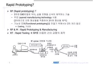
Rapid Prototyping (RP) A family of fabrication processes developed to make engineering prototypes in minimum lead time based on a CAD model of the item • Traditional method is machining • Can require significant lead-times – several weeks, depending on part complexity and difficulty in ordering materials • RP allows a part to be made in hours or days, given that a computer model of the part has been generated on a CAD system
Why is Rapid Prototyping Important? • Product designers want to have a physical model of a new part or product design rather than just a computer model or line drawing • Creating a prototype is an integral step in design • A virtual prototype (a CAD model of the part) may not be sufficient for the designer to visualize the part adequately • Using RP to make the prototype, the designer can see and feel the part and assess its merits and shortcomings
RP – Two Basic Categories: • Material removal RP - machining, using a dedicated CNC (computer numerical control) machine that is available to the design department on short notice • Starting material is often wax • Easy to machine • Can be melted and resolidified • The CNC machines are often small - called desktop machining • Material addition RP - adds layers of material one at a time to build the solid part from bottom to top
Starting Materials in Material Addition RP • Liquid monomers that are cured layer by layer into solid polymers • Powders that are aggregated and bonded layer by layer • Solid sheets that are laminated to create the solid part Additional Methods • In addition to starting material, the various material addition RP technologies use different methods of building and adding layers to create the solid part • There is a correlation between starting material and part building techniques
Steps to Prepare Control Instructions • Geometric modeling - model the component on a CAD system to define its enclosed volume • Tessellation of the geometric model - the CAD model is converted into a computerized format that approximates its surfaces by facets (triangles or polygons) • Slicing of the model into layers - computerized model is sliced into closely-spaced parallel horizontal layers
Solid Model to Layers Figure 34.1 Conversion of a solid model of an object into layers (only one layer is shown).
More About Rapid Prototyping • Alternative names for RP: • Layer manufacturing • Direct CAD manufacturing • Solid freeform fabrication • Rapid prototyping and manufacturing (RPM) • RP technologies are being used increasingly to make production parts and production tooling, not just prototypes
Classification of RP Technologies • There are various ways to classify the RP techniques that have currently been developed • The RP classification used here is based on the form of the starting material: • Liquid-based • Solid-based • Powder-based
Liquid-Based Rapid Prototyping Systems • Starting material is a liquid • About a dozen RP technologies are in this category • Includes the following processes: • Stereolithography • Solid ground curing • Droplet deposition manufacturing
Stereolithography (STL) RP process for fabricating a solid plastic part out of a photosensitive liquid polymer using a directed laser beam to solidify the polymer • Part fabrication is accomplished as a series of layers - each layer is added onto the previous layer to gradually build the 3-D geometry • The first addition RP technology - introduced 1988 by 3D Systems Inc. based on the work of Charles Hull
Stereolithography Figure 34.2 Stereolithography: (1) at the start of the process, in which the initial layer is added to the platform; and (2) after several layers have been added so that the part geometry gradually takes form.
Figure 34.3 A part produced by stereolithography (photo courtesy of 3D Systems, Inc.).
Facts about STL • Each layer is 0.076 mm to 0.50 mm (0.003 in to 0.020 in.) thick • Thinner layers provide better resolution and more intricate shapes; but processing time is longer • Starting materials are liquid monomers • Polymerization occurs on exposure to UV light produced by laser scanning beam • Scanning speeds ~ 500 to 2500 mm/s
Solid Ground Curing (SGC) Like stereolithography, SGC works by curing a photosensitive polymer layer by layer to create a solid model based on CAD geometric data • Instead of using a scanning laser beam to cure a given layer, the entire layer is exposed to a UV source through a mask above the liquid polymer • Hardening takes 2 to 3 s for each layer
Solid Ground Curing Figure 34.4 SGC steps for each layer: (1) mask preparation, (2) applying liquid photopolymer layer,(3) mask positioning and exposure of layer, (4) uncured polymer removed from surface, (5) wax filling, (6) milling for flatness and thickness.
Facts about SGC • Sequence for each layer takes about 90 seconds • Time to produce a part by SGC is claimed to be about eight times faster than other RP systems • The solid cubic form created in SGC consists of solid polymer and wax • The wax provides support for fragile and overhanging features of the part during fabrication, but can be melted away later to leave the free-standing part
Droplet Deposition Manufacturing (DDM) Starting material is melted and small droplets are shot by a nozzle onto previously formed layer • Droplets cold weld to surface to form a new layer • Deposition for each layer controlled by a moving x-y nozzle whose path is based on a cross section of a CAD geometric model that is sliced into layers • Work materials include wax and thermoplastics
Solid-Based Rapid Prototyping Systems • Starting material is a solid • Solid-based RP systems include the following processes: • Laminated object manufacturing • Fused deposition modeling
Laminated Object Manufacturing (LOM) Solid physical model made by stacking layers of sheet stock, each an outline of the cross-sectional shape of a CAD model that is sliced into layers • Starting sheet stock includes paper, plastic, cellulose, metals, or fiber-reinforced materials • The sheet is usually supplied with adhesive backing as rolls that are spooled between two reels • After cutting, excess material in the layer remains in place to support the part during building
Laminated Object Manufacturing Figure 34.5 Laminated object manufacturing.
Fused Deposition Modeling (FDM) RP process in which a long filament of wax or polymer is extruded onto existing part surface from a workhead to complete each new layer • Workhead is controlled in the x-y plane during each layer and then moves up by a distance equal to one layer in the z-direction • Extrudate is solidified and cold welded to the cooler part surface in about 0.1 s • Part is fabricated from the base up, using a layer-by-layer procedure
Powder-Based RP Systems • Starting material is a powder • Powder-based RP systems include the following: • Selective laser sintering • Three dimensional printing
Selective Laser Sintering (SLS) Moving laser beam sinters heat‑fusible powders in areas corresponding to the CAD geometry model one layer at a time to build the solid part • After each layer is completed, a new layer of loose powders is spread across the surface • Layer by layer, the powders are gradually bonded by the laser beam into a solid mass that forms the 3-D part geometry • In areas not sintered, the powders are loose and can be poured out of completed part
Three Dimensional Printing (3DP) Part is built layer-by-layer using an ink-jet printer to eject adhesive bonding material onto successive layers of powders • Binder is deposited in areas corresponding to the cross sections of part, as determined by slicing the CAD geometric model into layers • The binder holds the powders together to form the solid part, while the unbonded powders remain loose to be removed later • To further strengthen the part, a sintering step can be applied to bond the individual powders
Three Dimensional Printing Figure 34.6 Three dimensional printing: (1) powder layer is deposited, (2) ink-jet printing of areas that will become the part, and (3) piston is lowered for next layer (key: v = motion).
RP Applications • Applications of rapid prototyping can be classified into three categories: • Design • Engineering analysis and planning • Tooling and manufacturing
Design Applications • Designers are able to confirm their design by building a real physical model in minimum time using RP • Design benefits of RP: • Reduced lead times to produce prototypes • Improved ability to visualize part geometry • Early detection of design errors • Increased capability to compute mass properties
Engineering Analysis and Planning • Existence of part allows certain engineering analysis and planning activities to be accomplished that would be more difficult without the physical entity • Comparison of different shapes and styles to determine aesthetic appeal • Wind tunnel testing of streamline shapes • Stress analysis of physical model • Fabrication of pre-production parts for process planning and tool design
Tooling Applications • Called rapid tool making (RTM) when RP is used to fabricate production tooling • Two approaches for tool-making: • Indirect RTM method • Direct RTM method
Indirect RTM Method Pattern is created by RP and the pattern is used to fabricate the tool • Examples: • Patterns for sand casting and investment casting • Electrodes for EDM (Electric discharge machining)
Direct RTM Method RP is used to make the tool itself • Example: • 3DP to create a die of metal powders followed by sintering and infiltration to complete the die
Manufacturing Applications • Small batches of plastic parts that could not be economically molded by injection molding because of the high mold cost • Parts with intricate internal geometries that could not be made using conventional technologies without assembly • One-of-a-kind parts such as bone replacements that must be made to correct size for each user
Problems with Rapid Prototyping • Part accuracy: • Staircase appearance for a sloping part surface due to layering • Shrinkage and distortion of RP parts • Limited variety of materials in RP • Mechanical performance of the fabricated parts is limited by the materials that must be used in the RP process