Download
1 / 32
390 likes | 967 Views
Angle Modulation . Introduction. There are three parameters of a carrier that may carry information: Amplitude Frequency Phase Frequency and Phase modulation are closely related and grouped together as Angle modulation. Frequency Modulation.

E N D
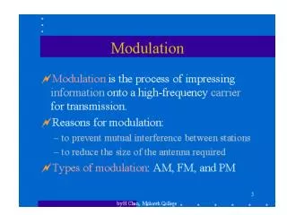
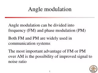
Introduction • There are three parameters of a carrier that may carry information: • Amplitude • Frequency • Phase • Frequency and Phase modulation are closely related and grouped together as Angle modulation
Frequency Modulation In this the instantaneous frequency of the carrier is caused to vary by an amount proportional to the amplitude of the modulating signal. The amplitude is kept constant.
Some key Observations • More complex than AM this is because it involves minute changes in frequency • Power in an FM signal does not vary with modulation • FM signals do not have an envelope that reproduces the modulation • FM is more immune to effects of noise
e(t) = E sin (t +) Frequency Deviation • Frequency deviation of the carrier is proportional to the amplitude of the modulating signal as illustrated kf= frequency deviation/V = kf kHz/V Maximum freq deviation
Deviation ratio Kf • This shift in frequency compared with the amplitude of the modulating voltage is called the deviation ratio. • Example • Given that the deviation constant is 1kHz/10mV, what is the shift in frequency for a voltage level of 50 mV? • Frequency deviation =
Mathematical Expression for FM e(t) = E sin (t +) Maximum freq deviation Where modulation index is
% modulation FM % Modulation = Actual freq deviation/ allowed freq deviation Example: An FM broadcast-band transmitter has a peak deviation of ±60 kHz for a particular input signal. Determine the percentage of modulation.
Important Definitions -Frequency Deviation is maximum departure of instantaneous freq. of FM wave from career frequency Maximum Freq of FM is fmax= fc+ is independent of modulating freq. and proportional to only amplitude of information Modulation index is proportional to deviation and inversely proportional to modulating freq. This decides the BW of the FM wave also decides the no of side bands In FM the modulation index can be greater than 1
DR =Maximum deviation /maximum modulating freq in FM is 75KHz is 15KHz Deviation Ratio
Examples In an FM system when the audio frequency is 300 Hz and the audio voltage is 2.0V, the deviation is 5kHz. If the audio voltage is now increased to 6V what is the new deviation? If the voltage is now increased to 9V and the frequency dropped to 100Hz what is the deviation? Find the modulation index in each case.
Find the carrier and modulating frequencies, the modulating index, and the max. deviation of an FM wave below. What power will the wave dissipate in a 10 ohm resistor? Compare this with: Modulating index =5 as given. Power,
J0Ec J1Ec J1Ec J2Ec J2Ec J3Ec J3Ec Fc-2fm fc Fc-3fm Fc-fm Fc+fm Fc+2fm Fc+3fm Frequency spectrum of FM Wave – Sin of sin function is solved by Bessel function
Jn Modulation index
Carson’s Rule This is an approximate method used to predict the required bandwidth necessary for FM transmission About 98% of the total power is included in the approximation.
What bandwidth is required to transmit an FM signal with intelligence at 12KHz and max deviation 24 kHz Consult Bessel function table to note that for modulating index of 2, components which exist are J1,J2,J3,J4 apart from J0. This means that apart from the carrier you get J1 at +/-10kHz, J2 at +/- 20kHz, J3 at +/- 30kHz and J4 at +/- 40 kHz. Total bandwidth is therefore 2x40=80kHz.
For an FM signal given by If this signal is input into a 30 ohm antenna, find • the carrier frequency • the transmitted power • the modulating index • the intelligence frequency • the required bandwidth using Carson's rule and tables • the power in the largest and smallest sidebands
AM Vs FM systems In both systems a carrier wave is modulated by an audio signal to produce a carrier and sidebands. The technique can be applied to various communication systems eg telephony and telegraphy Special techniques applied to AM can also be applied to FM Both systems use receivers based on the superheterodyne principle
In AM, the carrier amplitude is varied whereas in FM the carrier frequency is varied • AM produces two sets of sidebands and is said to be a narrowband system. FM produces a large set of sidebands and is a broad band system • FM gives a better signal to noise ratio than AM under similar operating conditions • FM systems are more sophisticated and expensive than AM systems
Transmitters In an AM transmitter, provision must be made for varying the carrier amplitude whilst for FM the carrier frequency is varied. AM and FM modulators are therefore essentially different in design. FM can be produced by direct frequency modulation or by indirectly phase modulation. The FM carrier must be high usually in the VHF band as it requires large bandwidth which is not available in the lower bands.
Receivers The FM and AM receivers are basically the same, however the FM receiver uses a limiter and a discriminator to remove AM variations and to convert frequency changes to amplitude variations respectively. As a result they (FM) have higher gain than AM. FM receivers give high fidelity reproduction due to their large audio bandwidth up to 15 kHz compared with about 8 kHz for AM receivers.
Frequency Modulation Index Another term common to FM is the modulation index, as determined by the formula:
Phase Modulation In phase modulation, the phase shift is proportional to the instantaneous amplitude of the modulating signal, according to the formula:
Relationship Between FM and Phase Modulation Frequency is the derivative of phase, or, in other words, frequency is the rate of change of phase The modulation index is proportional to frequency deviation and inversely proportional to modulating frequency
Modulating Signal Frequency Insert fig. 4.4
Converting PM to FM • An integrator can be used as a means of converting phase modulation to frequency modulation
This solution may be shown to be given by To evaluate the individual values of J is quite tedious and so tables are used.
Observations • Unlike AM where there are only three frequencies, FM has an infinite number of sidebands • The J coefficients decrease with n but not in any simple form and represent the amplitude of a particular sideband. The modulation index determines how many sideband components have significant amplitudes • The sidebands at equal distances from fc have equal amplitudes • In AM increase depth of modulation increases sideband power and hence total transmitted power. In FM total transmitted power remains constant, increase depth of modulation increases bandwidth • The theoretical bandwidth required for FM transmission is infinite.