Download
1 / 55
560 likes | 781 Views
Application of COLTRIMS to Study Collision Induced Dissociation of Multiply Charged Benzene. Giorgi Veshapidze , Haruo Shiromaru Tokyo Metropolitan University. Outline. Motivation Experimental method and apparatus Data handling methodology Doubly charged benzene Multiply charged benzene

E N D
Application of COLTRIMS to Study Collision Induced Dissociation of Multiply Charged Benzene Giorgi Veshapidze, Haruo Shiromaru Tokyo Metropolitan University
Outline • Motivation • Experimental method and apparatus • Data handling methodology • Doubly charged benzene • Multiply charged benzene • Multiply charged difluorobenzene • Summary and conclusions
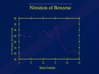
Motivation • Benzene Building block of many organic molecules • Low charge fragmentation Access to intermediate states • High charge fragmentation Access to initial Geometry • By varying the charge state and excitation, useful information might be gained.
TMU-ECRIS facility ZOO-RISE setup CEI setup
CEI = Coulomb Explosion Imaging • ZOO-RISE = ZOOmable Recoil Imaging with Secondary Electrons • Both are based on the application of Recoil Ion Momentum Spectroscopy (RIMS) method to the molecular fragmentation. • RIMS = Position-sensitive + Time Of Flight (TOF) measurement. • x, y, t px, py, pz or vx, vy, vz
RIMS principle PSD for recoil ions x, y and TOF Ions, with kinetic energy more than εmax can not be detected with 4π solid angle. • q = Ion charge • E = Extraction field strength • L = Flight length • R = PSD radius Increasing E or decreasing L shortens TOF, thus reducing time resolution. Initial velocity vectors are calculated by simple, classical-mechanical equations.
Differences between RIMS and CEI • Atomic target • Recoil ion energy < 1 eV • Single ion has to be detected. RIMS CEI • Molecular target • Fragment ion energy >1 eV or >>1 eV (depends on charge state). • Several fragment ions are to be detected in coincidence. 4π solid angle detection of fragment ions with energies > 1 eV is required for Coulomb Explosion Imaging.
PSD • Ring electrodes • Electro-magnetic coils • Aluminum plate • Magnetic field lines • Fragment ions • Secondary electrons ZOO-RISE Technique Trigger
Schematic diagram of electric potential inside drift tube +2200 V 0 V -300 V -2200 V Electrons, produced at aluminum plate, can reach PSD, while those, produced at collision region, are retarded. Aluminum plate PSD Collision region Mesh electrode
Triggering method T A = Projectile ion signal B = Fragment ion signal C = Stretched A T = Trigger position A Trigger if (C while B) B This method ensures that measurement is trigged only if projectile and fragment(s) are detected in coincidence C
Comparison BEFORE AFTER a) b) TOF Coincidence map for Ar8+ + N2 products. a) – conventional mode (fragment ions are detected on PSD), b) – ZOO-RISE mode (secondary electrons are detected on PSD).
Points to consider • Magnetic field at Aluminum plate and MCP surfaces should be as uniform as possible. Otherwise mapping might not be linear. • Due to non-vanishing ExB at non-uniform magnetic field region, secondary electrons may acquire considerable transverse velocity component. This will lower positional resolution.
Positional linearity d [mm] d [mm] TOF2 – TOF1 [ns] TOF2 – TOF1 [ns] Calculated Measured
Summary of benefits • Larger “detection area” for the same price. • Improved detection efficiency. • Photon imaging can be done in the same way. • Ion-Ion, Electron-Ion, Photon-Ion, Photon-Electron or Photon-Electron-Ion coincidence measurement can be done with single PSD.
Conventional PSD PSD MCP MBWC anode mesh Electron avalanche
Front view Rear view Electron avalanche should overlap several wedges, to obtain positional information.
New PSD MCP In magnetic field MBWC anode mesh Ceramic Plate with resistive layer Can be used in magnetic field.
MBWC and Resistive plate y x Resistive plate MBWC anode
The Mask and the Image a) b)
Data Analysis I Pre-onset level TOFexp
Doubly charged C6D6 • Only two charged fragments are produced • Only double coincidence study is necessary (and possible) to analyze fragmentation. • Branching ratios and KERs for various channels can be readily deduced. • Dissociation scheme can be studied.
[C3Dx -- C3Dy]2+ [C2Dx -- C4Dy]2+ [CD3 -- C5D3]2+ 2+ CD3+ + C5D3+ C2Dx+ + C4Dy+ C3Dx+ + C3Dy+
Specifics • Slow dissociation. • “Plenty” of time for rearrangement. • KER values are sensitive to the intermediate states. • Intermediate states can be studied.
Experimental conditions • Projectile pulse duration < 50 ns. • Maximal energy with 4π collection angle ~ 6 eV. • Projectile = H+ (15 keV) and Ar8+ (120 keV).
H+ + C6D6 C3D3+ or (C6D6)2+
H+ + C6D6 C5Dx+ C4Dx+ C3Dx+ C2Dx+ CDx+ D+ C3Dx+ C4Dx+ C2Dx+ D+ C5Dx+ CDx+
Molecular Fragments In each group, each parallel line corresponds to the different number of lost D atoms. Number of parallel lines CD3+ + C5D3+ C2Dx+ + C4Dy+ Excitation of the parent ion C3Dx+ + C3Dy+
To test our assumption that number of parallel lines corresponds to the vibrational excitation of target molecule, Ar8+ projectile was used. • Charge capture occurs at a larger distance and direct vibrational excitation would be smaller. • Decrease in the number of parallel lines is expected.
CD3+ + C5D3+ C2Dx+ + C4Dy+ C3Dx+ + C3Dy+ Ar8+ + C6D6 Only three lines Less excited than in H+ + C6D6 case
CD3+ + C5D3+ C2Dx+ + C4Dy+ C3Dx+ + C3Dy+ The trend Why different number of parallel lines?! As an excitation increases, fragmentation becomes more and more symmetric. Some similarity with nuclear fission.
Fragmentation Mechanism If the structure of parent ion changes 1. (C6D6)2+(C6D4)2+ + 2D (C2D2)+ + (C4D2)+ (C2D3)+ + (C4D3)+ 2. (C6D6)2+(C2D3)+ + (C4D3)+ (C4D2)+ + D (C2D2)+ + D KER depends on the number of lost D atoms E1 E2 E1’ + E2’ < E1 + E2 E2’ ΔE ΔE E1’ KER depends on the number of lost D atoms
CD3+ + C5D3+ C2Dx+ + C4Dy+ C3Dx+ + C3Dy+ KERs Expected difference of KER should have been ~ 10% but no difference is found C3D3+ + C3D3+ C3D+ + C3D+
Alternatives • If D-loss occurs just before dissociation No time for rearrangement KER does not depend on the number of lost D-s. • If D-loss occurs just after dissociation Fragments have not acquired significant kinetic energy yet No kinematic effect of D-loss KER does not depend on the number of lost D-s. • D-loss occurs ~ during dissociation.
Comparison of KERs C3Dx+ + C3Dy+ C2Dx+ + C4Dy+ CD3+ + C5D3+ Vibrational excitation leads to the increased bond lengths in the molecule Decreased KERs a) P.J. Richardson, J.H.D. Eland and P. Lablanquie, Organic Mass Spectrometry 21 (1986) 289-294.
Conclusions • Increased vibrational excitation leads to more symmetric fragmentation of (C6D6)2+. • D-loss occurs during fragmentation process. • KER trend for different ionization mechanism is consistent with the nature of excitation.
Multiply charged C6H6 • Faster dissociation • More Coulombic behavior • More charged fragments are available • Triple coincidence study is possible
CEI Setup PSD for fragment ions Triggering probability Number of ejected Auger electrons Number of captured electrons Charge state of the target molecule High charge states of target are preferentially detected Trigger
Experimental conditions • Continuous projectile beam. • Maximal energy with 4π collection angle > 20 eV. • Projectile = Ar8+ (120 keV).
Planarity test 123 n12 is perpendicular to v1 and v2 when v3 is coplanar to v1 and v2, it will be perpendicular to n12 cos θ123 = 0 v1, v2 and v3 are velocity vectors of first, second and third fragment ion, detected in coincidence
-1 -0.5 0 0.5 1 -1 -0.5 0 0.5 1 Results C2H4 C2H6 C6H6 Planar Non-planar Planar For planar molecules, velocity vectors of fragments are also co-planar.
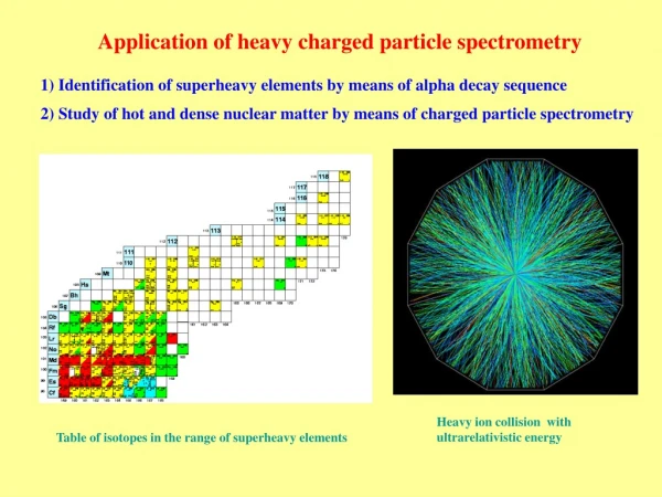
Charge state estimation Simulation Measured Charge states higher than 8+ are mainly populated in collisions.
Conclusions • Coulomb explosion Imaging of highly charged benzene was successfully done for the first time. • Quite sensitive tool to explore molecular geometry. • Might find application in isomer identification.
F F F F F F Angle between velocity vectors M. Nomura et. al. Int. J. Mass Spectrom. 235 (2004) 43-48
General conclusions • Compact type of PSD, usable in magnetic field, was developed. • New type of position-sensitive TOF analyser, nick-named ZOO-RISE, was developed and constructed. • Fragmentation of doubly charged benzene was studied and fragmentation-excitation trend was identified. • Coulomb Explosion Imaging was applied to the highly charged benzene and planar-nonplanar molecule distinction was made on the basis of coincident velocity vector correlation.
x y • -1.0 -0.6 -0.2 0.2 0.6 1.0 • -1.0 -0.6 -0.2 0.2 0.6 1.0 Positional resolution FWHM: Δx = 250μm Δy = 140μm
Position Calibration Edge of the aluminum plate Rexp Center of symmetry In our experiments K = 2.66 Typical image on PSD, when Helmholtz coils are switched off.
Branching ratios and KERs a) P.J. Richardson, J.H.D. Eland and P. Lablanquie, Organic Mass Spectrometry 21 (1986) 289-294.
θ and cos θ The probability that the angle between two vectors is between θ and θ+dθ in three dimensional space is Histogram of θ will be Histogram of cosθ will be