Download
1 / 29
290 likes | 503 Views
BNL - FNAL - LBNL - SLAC. Model Quadrupoles DOE Review of the LHC Accelerator Research Program June 19-20, 2008 Gian Luca Sabbi. Outline. Technology Quads – TQ: Goals Design Model Magnet Program Test Results & Analysis Status and Next steps High Gradient/Aperture Quads – HQ:

E N D
BNL - FNAL - LBNL - SLAC Model Quadrupoles DOE Review of the LHC Accelerator Research Program June 19-20, 2008 Gian Luca Sabbi
Outline • Technology Quads – TQ: • Goals • Design • Model Magnet Program • Test Results & Analysis • Status and Next steps • High Gradient/Aperture Quads – HQ: • Goals and R&D Issues • Coil and Structure Design • Progress toward start of fabrication • Status and next steps
Technology Quadrupoles (TQ) • Technical objective: develop technology base for the Long Quadrupole • Evaluation of conductor and cable performance • Development and optimization of coil fabrication procedures • Comparison of mechanical design concepts & support structures • Magnet parameters: • 1 m length, 90 mm aperture, cos2q coil geometry • Maximum gradient 200-260 T/m,10-13 T coil peak field • Goal: predictable and reproducible performanceabove 200 T/m • Two series of models, same coil design, different mechanical support: • TQC models: collar & stainless steel shell; low axial pre-load • TQSmodels: aluminum shell over iron yoke; high axial pre-load
Yoke Pad Key Shell Axial rod Filler TQC and TQS Designs TQC (Collar) TQS (Shell) • Stainless steel collars and skin • Control spacers to limit pre-load • Full pre-load at room temperature • End support plates, low pre-load • Aluminum shell over iron yoke • Assembly with bladders and keys • Full preload after cool-down • Rods/plates for high axial pre-load
TQ Conductor and Coils • TQ01: OST-MJR strand • TQ02: OST-RRP strand • 27-strand, 10.05 mm width • Insulation: S-2 glass sleeve • Double-layer, cos2q coils • One wedge/octant Winding & curing (FNAL - all coils) Reaction & potting (LBNL - all coils)
TQ Short Sample Limit MJR strand (TQ01 Models) Jc = 1.9 kA/mm2 (12 T, 4.2 K) RRP strand (TQ02 models) Jc = 2.7 kA/mm2 (12 T, 4.2 K) • TQC iron yoke is located further away from the coil than TQS (SS collar) • - Causes shallower load line, lower short sample gradient • From TQC01b, iron yoke was extended above the ends for mechanical reasons • - End peak field increase causes further loss of short sample gradient Same fraction of short sample results in ~6% lower gradient for TQC than TQS
TQC Tests New models & virgin coils are in bold font. Rebuilt models & pre-trained coils are in italic font.
TQS Tests New models & virgin coils are in bold font. Rebuilt models & pre-trained coils are in italic font.
Performance Expectations • TQ02 models should perform better than TQ01 models • Experimental feedback, optimization of design and procedures • RRP conductor has much higher critical current than MJR • Revised models should perform better than new models • Use best coils from previous tests • Optimized pre-loading conditions • Revised models with no new coils should have faster training • Nb3Sn coils retain their training • Performance at 1.9K should be better than at 4.4K Significant departures from these expected trends in some of the tests
Quench Training (New Models) Ramp rate, intermediate temperature and spurious (system triggered) quenches are not included
Quench Training (Rebuilt Models) Ramp rate, intermediate temperature and spurious (system triggered) quenches are not included
TQ Quench Performance Summary (*) Highest Quench value includes all Training, Ramp Rate & Intermediate Temperature Quenches
TQC Models Analysis TQC01a: Viability of collaring process demonstrated Low preload limited the quench plateau in TQC01a at 4.5K and resulted in outer layer mid-plane damage at 1.9K at the end of magnet test. TQC01b: Analysis incorporated plastic coil behavior, resulting in appropriate preload. Reached 88% of its short sample gradient at 4.5K and 92% at 1.9K. TQC02E: Coils re-used from TQS02a, collared without damage. Achieved 90% of its short sample gradient at 4.5K and 81% at 1.9K After disassembly, coils were re-used in TQS02b/c, with no indication of degradation during assembly, testing or disassembly of TQC structure.
TQC Models Analysis (2) TQC02a: TQC02a was first collared in March 2007: results from strain gauges as well as collar deflection measurements were consistent with analysis. The magnet was re-assembled in November 2007 with increased preload during the collaring phase. The reassembled magnet included two new coils, replacing two that may have been damaged due to a misplaced mid-plane shim during the initial assembly. Limited quench plateau in the new coils indicates probable degradation during construction due to higher collaring preload and large increments during early collaring steps. Return to TQC01b preload parameters and additional early collaring steps in TQC02b will allow return to TQC02E/TQC01b performance or better.
TQS Models Analysis • TQS01 (a,b,c): • Quenches originated at pole gaps, where high axial tension occurred • 3D FEA+SG data guided the change from Bronze to Titanium poles • TQS02 (a,b,c): • New Titanium poles eliminated pole-gap quenches • All models used the same structure and loading conditions • Performance limits in each model are in specific coils/locations: • TQS02a: limited by coil 21 at outer layer pole (both 4.4K & 1.9K) • TQS02b: limited by coil 29 at end of straight (both 4.4K & 1.9K) • TQS02c: limited by coil 23 at inter-layer ramp (both 4.4K & 1.9K) • All models used the same conductor and heat treat • For TQS02b, weakness could be traced back to coil winding phase • Ramp area limiting TQS02c is also problematic (geometry, handling) • TQS02 models identified areas for improving coil design and fabrication
TQ Summary • TQC: • Incorporation of analysis using plastic coil behavior and new coil measurement techniques provide tools for control of preload • Collaring parameters and procedures established through model program • Although the maximum gradient reached by TQC models is lower than in TQS, it corresponds to a similar fraction of the short sample limit • TQS02a coils were not significantly degraded after collaring and de-collaring in the TQC structure • TQS: • Demonstrated accurate, repeatable control of warm and cold pre-load • Delivered safe, fast assembly and disassembly for all 6 models • Training starts high and improves rapidly to maximum; no retraining • Reliable structure performance allows to identify conductor/coil issues • Selectively replaced coils to understand limits and improve coil quality • S02 models consistently surpassed the 200 T/m target at 4.4K & 1.9K • TQS02c never quenched below 200 T/m during 4.4K and 1.9K training
TQ Next Steps • TQS02: additional tests with modified loading conditions (e.g. end pre-load) will be performed at CERN • Helene Felice (Toohig Fellow) is playing a key role in coordinating planning, testing and analysis with CERN • TQC02b: currently under construction at FNAL. It will be tested to understand conductor properties and verify refined collaring procedures • Four new coils will be fabricated using 108/127 strand • Cable fabrication completed • Winding/reaction/potting before the end of the year • Plan to assemble first as a TQS then as a TQC
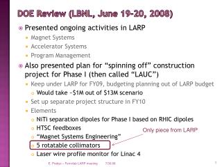
QA and HQ Goals QA: This series of ~4 m long quads will be designed using the parameters and accelerator quality specifications of the Phase 1 NbTi quads (except for length), to facilitate their evaluation for use in the LHC. The goal is to demonstrate large performance margins with respect to the NbTi quads, on the timescale of the Phase-1 upgrade. HQ: The HQ (High gradient/aperture Quad) series of short models will be used to develop the design of the mechanical support structure and the coils of QA. The full set of accelerator magnet features will be gradually incorporated into successive magnets in this series. Representatives from each Lab coordinate the mechanical design features
Phase 1 NbTi IR Quad Development Case 1: “special grading”: Aperture: 120 mm Nb turn of cable 1: 19 Nb turn of cable 2: 19 SS Gradient: 152.8 T/m Case 2: “normal grading”: Aperture: 120 mm Nb turn of cable 01/coil: 18 Nb turn of cable 02/coil: 17 SS gradient: 152.1 T/m P. Fessia, WAMSDO • Magnet aperture will be defined in the conceptual design report (June 08) • Jan. 08: considering values between 90 and 140 mm • May 08: considering values between 110 and 120 mm
350 350 Bpk ~15 T LBNL & INFN [3] FNAL[4] HQ HQ 90 300 300 [11] HQ 114 KEK & FNAL KEK & FNAL 250 250 NbTi LHC IR [1] NbTi LHC IR TQ [8] TQ [8-9] - [9] Short Sample Gradient [ T/m ] Short Sample Gradient [ T/m ] & LQ [10] LQ [10] HQ 134 200 200 [1] LHC Design Report [2] Ostojic et al, PAC05 [3] Caspi et al, MT-15 [4] Sen et al, PAC-01 [5] Zlobin et al, EPAC02 [6] Sabbi et al., ASC-02 [7] Todesco et al, PRST NbTi [2] - - 150 150 [8] Bossert et al., ASC-06 [9] Caspi et al., ASC-06 [10] Ambrosio et al, ASC06 [11] Sabbi et al, ASC06 NbTi [7] 100 100 50 50 70 70 90 90 110 110 130 130 150 150 Coil Aperture [ mm ] Coil Aperture [ mm ] HQ Design Space
HQ-114 HQ-134 Optimized HQ Cross-Sections
-100 MPa -85 MPa -2 MPa -171 MPa -187 MPa -177 MPa Coil Design Optimization Mechanical considerations are driving the HQ coil cross-section design • TQS (1-meter): • - 90 mm aperture • - 12 T peak field • 240 T/m • Fq Layer 1 = -1.5 MN/m • Fq Layer 2 = -1.02 MN/m • LQS (3.6-meter): • - 90 mm aperture • - 12 T peak field • 240 T/m • Fq Layer 1 = -1.5 MN/m • Fq Layer 2 = -1.02 MN/m • HQ (1-meter) • - 114 mm aperture • - 15 T peak field • 230 T/m • Fq Layer 1 = -2.5 MN/m • Fq Layer 2 = -2.99 MN/m 20 MPa 20 MPa 20 MPa Key optimization Xsection optimization
Cable Prototypes and Test Winding • First pass: 8 cable samples made • End parts designed for prelim. cross-sections • Poles fabricated using rapid prototyping • Two turns wound with 30 lb of cable tension • Samples rated for winding characteristics • Cables also evaluated for critical current • Feedback to cable & cross-section design • Baseline cable selected, longer length made • Further optimization in the near future
HQ Tooling Coil Winding Coil Curing • Conceptual design and CAD models completed, obtained quotes from vendors • Parametric spreadsheets to control coil build and relevant dimensions • Final drawings based on aperture determination, procurements will follow
Assembly Cool-down Excitation -77 MPa -35 MPa -176 MPa -133 MPa -177 MPa -136 MPa Mechanical Design Concept Guidelines: Full contact between pole and coil at short sample (200 – 230 T/m) Optimization of the mechanical stress in the coil during bladder operation: bladder location Optimization of the mechanical stress in the coil after cool-down and during excitation: key location Alignment with gradual implementation Preliminary results: Coil stresses can be maintained at safe levels up to the short sample limit
Shell Master Bladder Pad Coil Yoke Mechanical Assembly
Model Magnet Budget • FY08 budget: • Supported completion of TQC02a, TQC02e • No funding for TQS02b, TQS02c (supported by LBNL core program and CERN) • No funding for TQC02b (supported by FNAL core program) • Supported fabrication of 4 new TQ coils using 108/127 conductor • HQ funding directed toward magnet design, fabrication of tooling and coil parts • FY09 preliminary proposal & cost estimate (under discussion): • Fabrication and test of the first HQ model: 1.8 M$ • Start of coil fabrication for second HQ model: 0.4 M$ • No funding for TQ (core program support)
Summary • TQ Models: • The main TQ goal was achieved: • Surpassed 200 T/m with 10% margin • Consistent, reproducible results obtained in several models • However, no convergence yet on structure evaluation and selection • HQ models: • Goals and strategy for HQ and QA have been clearly defined • Planning to match the “Phase 1” short quadrupole development • Considerable progress in FY08 on magnet and tooling design • High field design is best suited to fully exploit Nb3Sn properties • Unique opportunity to qualify Nb3Sn magnets for use in LHC • Significant support required to complete first model in Sept. 2009