Download
1 / 35
350 likes | 545 Views
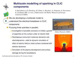
Flyura Djurabekova, Helga Timkó, Aarne Pohjonen, and Kai Nordlund. Multiscale modelling of electrical breakdown. Helsinki Institute of Physics and Department of Physics University of Helsinki Finland. Outline. What is the problem? Plasma onset by the external electric field

E N D
Flyura Djurabekova, Helga Timkó, Aarne Pohjonen, and Kai Nordlund Multiscale modelling of electrical breakdown Helsinki Institute of Physics and Department of Physics University of Helsinki Finland
Outline • What is the problem? • Plasma onset by the external electric field • Electrodynamics + Molecular Dynamics (ED+MD ) code (benefits/drawbacks) • Plasma burning • Surface cratering
Detecting the problem… Click! Click!
The scale of the problem About 50 km length?
Electrical Breakdown in multiscale modeling approach Stage 1: Charge distribution @ surface Method: DFT with external electric field ~few fs N Stage 2:Atomic motion & evaporation Method: Hybrid ED&MD model ~few ns P L A S M A O N S E T F Classical MD Solution of Laplace equation Stage 3: Evolution of surface morphology due to the given charge distribution Method: Kinetic Monte Carlo ~ sec to hours N Feedback: Electron & ion & cluster emission ions Stage 4: Plasma evolution, burning of arc Method: Particle-in-Cell (PIC) F ~10s ns Feedback: Energy & flux of bombarding ions Stage 5: Surface damage due to the intense ion bombardment from plasma Metod: Arc MD ~100s ns F
Plasma onset or How does all start???
+ + + + + + + + How do we introduce the external electric field? Macroscopic field to… Gauss law states Due to the external electric field the surface attains charge …the atomic level: Two electric forces modify the motion of charged atoms: +
Simulation approach Now ElectroDynamics+Molecular Dynamics (ED+MD) code to simulate the effect of the electric field WORKS! The distribution of the field near the surface is the solution of Laplace’s equation Multigrid solver is implemented. The calculation of the single step speeded up by 2-3 orders of magnitude! with mixed boundary conditions φ=const (conducting material) surface with an arbitrary morphology
On the positive side… • What can we benefit from ED+MD code? • Determine the charges gained by surface atoms due to the external electric field • Estimate the possible morphologies of surfaces formed due to the electric field • Simulate the field emission of the atoms/clusters at high gradient electric field, as well as the evaporation of atoms from the rough features formed on the surface at the lower fields
Limits… • Where are we limited in these simulations? • Diffusion process is too long to be treated by MD code. • Solution: if needed, the other methods for the longer time span (KMC, for instance) can be applied • Polycrystal structures can not be considered at the moment, since Laplace equation is solved for the uniform surface (single crystal) • Solution: we can consider different faces for the surface and, then, take the statistical average of the field effect
+ + + + + + + + Stresses due to the field • The main agreement in the field is that the rapid releasing of microstresses, which is generally present on grain boundaries and can be enhanced by any external agents as mechanical treatment or T-cycling, the migration of defect complexes is stimulated. • The strain by the huge electric field can cause the dislocation motion and redistribution of the microstress. → E STRESS =0E2/Y
Would it be some Taylor cones? • It is also known that flat liquid conducting surfaces form cones under electric fields • The tip of the cone emits atoms or droplets • This is industrially used in so called electrosprays • Could this happen also on solid surfaces?? • With a surface viscosity induced by a high adatom concentration due to the electric field, perhaps • But unlikely this would be large enough at room temperature [G. Taylor, Proc. Roy. Soc. London. Ser. A280 (1964) 383] [www.sisweb.com/lc/electrospray-tip.htm]
Solution of 3d Laplace equation for the surface with the tip of 20 atomic layers (color represents the charges)
eV eV Activation energy of direct field emission of atoms
Adatoms on the surface We analyzed only two different faces (100) and (111). The difference is evident. Closer packed face (111) less affected by the field.
Summary • ED+MD code is working and giving sensible results! • We simulated the case of direct field emission, which corresponds to the experimental data • At the elevated temperatures the sharp tip of ~300 atoms emitted atoms/clusters already at 1 GV/m • The roughening must depend on the surface orientation (111) the closest pack shows the least respond to the field effect.
Plasma Arcs or Sparks?
Background:Vacuum sparks • A vacuum spark is an electrical plasma discharge emerging from a rough surface feature under high electric field gradients • Onset not understood at all (cf. beginning of talk) • After that somewhat understood: [R. Behrisch, in Physics of Plasma-wall Interactions in Controlled fusion, NATO ASI series B 131 (1986) 495]
How to simulate plasma burning? • Particle-in-cell (PIC) simulations of the spark plasma (will hear more in close future by Helga T.) This part of project has been started very recently, but we have some preliminary results by Konstantin Matyash and Ralf Schneider from Max-Planck Institut für Plasmaphysik in Greifswald. Their results give us: • as output e.g. ion and neutral flux and energy distribution towards surface • Conditions chosen to be those corresponding to sparking experiments at CERN for development of CLIC
PIC simulations • The 1D PIC simulations give the plasma density time evolution above the surface:
Note flux value !! PIC simulation output • The PIC simulations gave particle flux and energies Note huge peak around ion energy of 8 keV due to plasma sheath potential!
Surface damage while arcing
Background: Spark cratering • The sparking leads to a plasma-wall interactions which somehow produces a large (~ 0.1 – 100 µm) crater. • Classical explanation: surface heating by ions and electrons => massive evaporation [http://www.uni-saarland.de/fak8/fuwe/fuwe_de/Forschung/electroden/Indexi.htm]
Multiscale modelling of sparks:Classical MD simulations • MD simulations of surface bombardment on a given area A • Ion flux and energy distribution corresponded exactly to that from PIC simulations! • Flux of ~1025 on eg. r=15 nm circle => one ion/20 fs!! Top view Side view
Multiscale modelling of sparks:Classical MD simulations • With this huge flux and energy distribution, several overlapping cascades lead to huge heating and cratering • This is not just classical evaporation, but a heat spike! Simulation time of 36 hours on2000 processors
Multiscale modelling of sparks:Classical MD simulations • The end result is cratering
Cu Mo W Multiscale modelling of sparks:Comparison of materials
Comparison with experiments • Experiments show a wide variety of spark crater sizes • But they appear to be self-similar over size scales:
Comparison with experiments • Due to the self-similarity over size scales, we can compare our craters with experiments Simulation Experiment [R. Behrisch, in Physics of Plasma-wall Interactions in Controlled fusion, NATO ASI series B 131 (1986) 495]
Conclusion • Vacuum spark craters are formed by an overlapping heat spike process (if the electric field is high enough) • Ions accelerated in plasma sheath potential to energies ~ 10 times higher than the electric field gradient itself
Summary & Outlook • The model comprises the different physical processes (nature and time wise) probable right before, during and after an electrical breakdown event. • All the parts of the general model are started in parallel. We start, continue and develop intense activities to cover all possible aspects. • Nevertheless, currently, there are blocks in model lacking man-power. • On filling these gaps too we strongly believe to be capable to gain comprehensive insight to the puzzle of electrical BREAKDOWN. • Effect of rf-field is to be included next.
Thank you! Any recommendation?