Download
1 / 34
440 likes | 926 Views
25. Electric Circuits. Circuits, Symbols, & Electromotive Force Series & Parallel Resistors Kirchhoff’s Laws & Multiloop Circuits Electrical Measurements Capacitors in Circuits. Festive lights decorate a city. If one of them burns out, they all go out.

E N D
25. Electric Circuits Circuits, Symbols, & Electromotive Force Series & Parallel Resistors Kirchhoff’s Laws & Multiloop Circuits Electrical Measurements Capacitors in Circuits
Festive lights decorate a city. If one of them burns out, they all go out. Are they connected in series or in parallel?
Electric Circuit = collection of electrical components connected by conductors. Examples: Man-made circuits: flashlight, …, computers. Circuits in nature: nervous systems, …, atmospheric circuit (lightning).
25.1. Circuits, Symbols, & Electromotive Force Common circuit symbols All wires ~ perfect conductors V = const on wire Electromotive force (emf) = device that maintains fixed V across its terminals. E.g., batteries (chemical), generators (mechanical), photovoltaic cells (light), cell membranes (ions).
m~ q Collisions ~ resistance g ~ E Lifting ~ emf Ideal emf : no internal energy loss. Energy gained by charge transversing battery = qE ( To be dissipated as heat in external R. ) Ohm’s law:
GOT IT? 25.1. The figure shows three circuits. Which two of them are electrically equivalent?
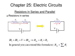
25.2. Series & Parallel Resistors Series resistors : I = same in every component Same q must go every element. For n resistors in series: n = 2 : Voltage divider
Example 25.1. Voltage Divider A lightbulb with resistance 5.0 is designed to operate at a current of 600 mA. To operate this lamp from a 12-V battery, what resistance should you put in series with it? lightbulb Voltage across lightbulb = Most inefficient
GOT IT? 25.2. Rank order the voltages across the identical resistors R at the top of each circuit shown, and give the actual voltage for each. In (a) the second resistor has the same resistance R, and (b) the gap is an open circuit (infinite resistance). 6V 3V 0V
Real Batteries Model of real battery = ideal emf E in series with internal resistance Rint . I means V drop I Rint Vterminal < E
Example 25.2. Starting a Car Your car has a 12-V battery with internal resistance 0.020 . When the starter motor is cranking, it draws 125 A. What’s the voltage across the battery terminals while starting? Battery terminals Voltage across battery terminals = Typical value for a good battery is 9 – 11 V.
Parallel Resistors Parallel resistors: V = same in every component For n resistors in parallel :
GOT IT? 25.3. The figure shows all 4 possible combinations of 3 identical resistors. Rank them in order of increasing resistance. 3R/2 3R R/3 2R/3 2 1 4 3
Analyzing Circuits • Tactics: • Replace each series & parallel part by their single component equivalence. • Repeat.
Example 25.3. Series & Parallel Components Find the current through the 2- resistor in the circuit. Equivalent of parallel 2.0- & 4.0- resistors: Equivalent of series 1.0-, 1.33- & 3.0- resistors: Total current is Voltage across of parallel 2.0- & 4.0- resistors: Current through the 2- resistor:
GOT IT? 25.4. • The figure shows a circuit with 3 identical lightbulbs and a battery. • Which, if any, of the bulbs is brightest? • What happens to each of the other two bulbs if you remove bulb C? dimmer brighter
25.3. Kirchhoff’s Laws & Multiloop Circuits • Kirchhoff’s loop law: • V = 0 around any closed loop. • ( energy is conserved ) • Kirchhoff’s node law: • I = 0 at any node. • ( charge is conserved ) This circuit can’t be analyzed using series and parallel combinations.
Multiloop Circuits Problem Solving Strategy: INTERPRET ■ Identify circuit loops and nodes. ■ Label the currents at each node, assigning a direction to each. • DEVELOP • ■ Apply Kirchhoff ‘s node law to all but one nodes. ( Iin > 0, Iout < 0 ) • ■ Apply Kirchhoff ‘s loop law all independent loops: • Batteries: V > 0 going from to + terminal inside the battery. • Resistors: V = I R going along +I. • Some of the equations may be redundant.
Example 25.4. Multiloop Circuit Find the current in R3 in the figure below. Node A: Loop 1: Loop 2:
Application: Cell Membrane Hodgkin-Huxley (1952) circuit model of cell membrane (Nobel prize, 1963): Resistance of cell membranes Membrane potential Time dependent effects Electrochemical effects
25.4. Electrical Measurements A voltmeter measures potential difference between its two terminals. Ideal voltmeter: no current drawn from circuit Rm =
Conceptual Example 25.1. Measuring Voltage What should be the electrical resistance of an ideal voltmeter? An ideal voltmeter should not change the voltage across R2 after it is attached to the circuit. The voltmeter is in parallel with R2. In order to leave the combined resistance, and hence the voltage across R2 unchanged, RV must be .
Example 25.5. Two Voltmeters You want to measure the voltage across the 40- resistor. What readings would an ideal voltmeter give? What readings would a voltmeter with a resistance of 1000 give? (a) (b)
GOT IT? 25.5. If an ideal voltmeter is connected between points A and B in figure, what will it read? All the resistors have the same resistance R. ½ E
Ammeters An ammeter measures the current flowing through itself. Ideal voltmeter: no voltage drop across it Rm = 0
Ohmmeters & Multimeters An ohmmeter measures the resistance of a component. ( Done by an ammeter in series with a known voltage. ) Multimeter: combined volt-, am-, ohm- meter.
25.5. Capacitors in Circuits Voltage across a capacitor cannot change instantaneously.
The RC Circuit: Charging C initially uncharged VC = 0 Switch closes at t = 0. VR (t = 0) = E I (t = 0) = E / R C charging: VC VR I Charging stops when I = 0. VR but rate I but rate VC but rate
VC ~ 2/3 E I ~ 1/3 E/R Time constant = RC
The RC Circuit: Discharging C initially charged to VC = V0 Switch closes at t = 0. VR = VC = V I0 = V0/ R C discharging: VC VR I Disharging stops when I = V = 0.
Example 25.6. Camera Flash A camera flash gets its energy from a 150-F capacitor & requires 170 V to fire. If the capacitor is charged by a 200-V source through an 18-k resistor, how long must the photographer wait between flashes? Assume the capacitor is fully charged at each flash.
RC Circuits: Long- & Short- Term Behavior For t << RC: VC const, C replaced by short circuit if uncharged. C replaced by battery if charged. For t >> RC: IC 0, C replaced by open circuit.
Example 25.7. Long & Short Times • The capacitor in figure is initially uncharged. • Find the current through R1 • the instant the switch is closed and • a long time after the switch is closed. (a) (b)
GOT IT? 25.6. • A capacitor is charged to 12 V • & then connected between points A and B in the figure, • with its positive plate at A. • What is the current through the 2-k resistor • immediately after the capacitor is connected and • a long time after it’s connected? 6 mA 2 mA