Download
1 / 15
150 likes | 279 Views
A 10 GeV, 4 MW, FFAG, Proton Driver at 50 Hz. G H Rees, RAL. Non-scaling, Non-linear FFAGs. Categories for FFAG Lattice Cells of Five Magnets: 1. IFFAG: isochronous, no Q v =n and 2Q v =n crossing 2. IFFAGI: IFFAG with combined function insertions

E N D
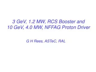
A 10 GeV, 4 MW, FFAG,Proton Driver at 50 Hz G H Rees, RAL
Non-scaling, Non-linear FFAGs Categories for FFAG Lattice Cells of Five Magnets: 1. IFFAG: isochronous, no Qv=n and 2Qv=n crossing 2. IFFAGI: IFFAG with combined function insertions 3. NFFAG: non-isochronous, high/imag -t, no Q var’n 4. NFFAGI:NFFAG with insertions, some Qh variation 1 and 2: rapid acceleration of muons or electrons 3 and 4 :high power proton drivers or medical rings
4 MW Proton Driver Arrangement Muon yields optimal for 6 - 10 GeV (S Brooks, RAL) Choose: 10 GeV, 50 Hz to reduce target shock 3 GeV booster for 3 – 10 GeV NFFAGI 2, 25 Hz or 1, 25 Hz booster (R =2.2Rb) 0.18 GeV H‾ linac for low bunch areas 5 bunches at h = 5 for RCS booster(s) Transfer: 5 (1013 protons/bunch) to the NFFAGI Bunch to: 1 ns (rms) adiabatically (h = 33 & 198)
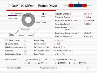
Longitudinal bunch area The longitudinal bunch area (in eV sec) is: A = (8Rα/(ch)) ((2V(I-sc)Eo) / (h))½ For a small longitudinal bunch area, choose a low value of injection energy and ring radius ChooseEo ( - 1)= 0.18 GeV andRb 50.0 m Choose the bunch & harmonic number (h) = 5 Compressed bunch area needed 0.66 eV sec
4 MW, Proton Driver Layout 0.18 GeV H ‾ Linac 0.18 GeV H ‾ Achromat 3 GeV, 50 Hz, h =5, RCS (1 at 50 Hz, or 2 at 25 Hz) 10 GeV, 50 Hz, N = 5, NFFAGI with 1013 protons per bunch
NFFAGI Design Criteria For compression of the 5 bunches at 10 GeV: Design for a gamma-t value at 10 GeV 20 Design for longitudinal bunch areas 0.66 eV s Adiabatic acceleration & comp. with h = 33, 198 Design the NFFAG ring with lattice insertions, to ease injection, ejection & beam loss collection Use two insertions to allow most flexibility, eg: 21 normal and 13 insertion cells per insertion
Acceleration and Compression Systems Driver-booster circumference ratio: 2.2 to 1 Booster rf range (h=5): 2.6164 to 4.670 MHz Driver rf range (h=33): 14.011 to 14.370 MHz Compression frequency (h=198): 86.222 MHz Peak accelerating voltage per turn: 1.0 MV Peak compression voltage per turn: 2.56 MV
Lattice Cell Options Normal cell Insertion cell Magnet types Doublet D D1 + T0 + D2 2 + 7 Triplet T T1 + T2 + T1 2 + 4 Pumplet P1 P2 3 + 3 Easiest solution is to match P1 and P2 pumplet cells: • P1 has a smaller β-range than either D or T • The insertion has only one type of cell, P2 • P2 has the smallest closed orbit “lever arm” No 2 dispersion suppressors, as too many are needed
10 GeV, Normal & Insertion Cell Layouts bd(-) BF(±) BD (+) BF(±) bd(-) O0.5 0.50.5 0.5O 0.60 1.25 1.9 1.25 0.60 0.651 Normal cell (5.294º, 8.902 m) 0.651 2.2 Insertion cell (5.294º, 12.00 m) 2.2 There are two superperiods of 21 normal & 13 insertion cells At 10 GeV: Qv= 13.72, Qh = 19.36, -t= 20.4, R = 109.17 m
NFFAGI Lattice Design Use equal bend, normal and insertion, pumplet cells Arrange ~ matching for a normal and insertion cell Arrange integer, insertion tunes eg Qh = 4 & Qv = 3 The normal cells in an insertion are then matched Seek unchanged closed orbits on adding insertions by varying the normal cell field gradients and tunes Then, dispersion match is almost exact for insertions Small ripple remains in βh and βv (max) in insertions
Non-Linearity Compensation Crossing of the 3rd order resonance: 3Qh= 58 • Insertion and arc 3(Qh ) values: 3Qh= 3(4, 5⅔ ) • Hence, no 3rd order excitation for: 3Qh= 58 Crossing of 4th order resonance: 2Qh + 2Qv = 66 • Insertion and arc values for: 2(Qh + Qv )= 2(7, 9½ ) • So, no 4th order excitation for: 2Qh + 2Qv = 66 Crossing of the 4th order resonance: 4Qh= 77 • Insertion and arc 4(Qh ) values: 4Qh = 4(4, 5⅝ ) • Some small 4th order excitation for: 4Qh= 77
NFFAGI Lattice Results Satisfactory matching at the 24 reference energies: 10.0…..6.8, 6.5…..5.0, 4.75…..4.0, 3.8…..3.0 GeV. Qv =13.72 throughout the 3 to 10 GeV energy range. Dispersion match is found by varying K(bd) and h: T =10.0……6.8, 6.5…. 5.0, 4.75..4.0, 3.8…3.0 GeV Qh=19.36, 19.31, 19.3, 19.29, 19.2, 19.2, 19.2, 19.2 Gamma-t becomes imaginary for the low energies
Combined Function Magnet Fields (T) Magnets Insertion Normal cell bd -1.70 to -1.18 -1.70 to -0.98 BF 1.75 to -0.15 1.75 to -0.27 BD 0.54 to 1.55 0.54 to 1.59 Tmax bending ratios; bd : BF : BD ~ - 0.47 : 1.0 : 0.23 (Ratios in muon ring; bd : BF : BD ~ - 1.0 : 1.0 : 1.0)
Beam Loss Collimators Vertical: • Locate in 4, adjacent, long, insertion straights • Use 1, primary and 3, secondary, 5 kW collimators • Use tapered units for lower, high energy acceptance Horizontal: • Locate in the first three, vertical, collimator straights • Use 1, primary and 3, secondary, 5 kW collimators • Use angled units for collimation at 3 and 10 GeV
10 GeV NFFAGI versus RCS Pros: Allows acceleration over more of the cycle, No need for ac magnet p/s or ceramic chamber, Gives more flexibility for the holding of bunches, Required is one NFFAGI ring, but two RCS(s), Allows operation at 50 Hz instead of at 25 Hz, with 5 1013 ppp at target, instead of 1014 ppp. Thus, there is half the target shock per pulse. Cons: needs a larger (~ 0.33 m) radial aperture