Download
1 / 11
110 likes | 253 Views
Magnet Safety Systems – Magnet Common Project E. Sbrissa, G. Olesen – CERN/EP. 2.3 Magnet Safety System description

E N D
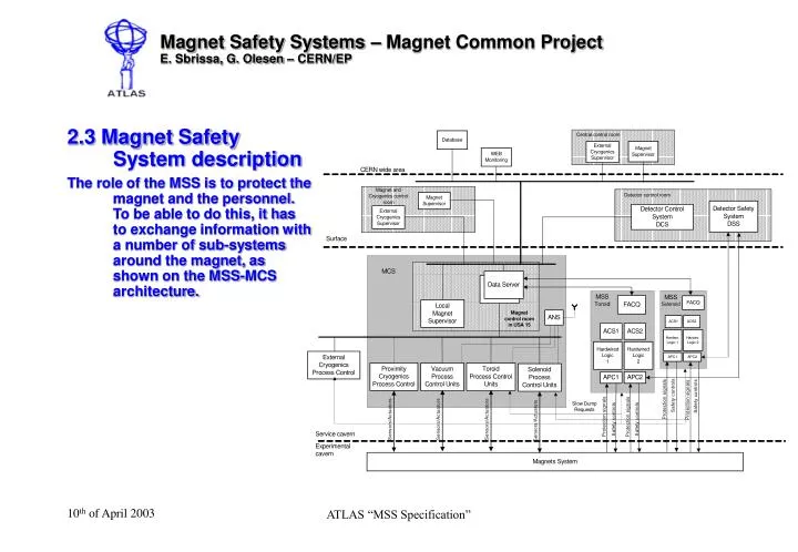
Magnet Safety Systems – Magnet Common ProjectE. Sbrissa, G. Olesen – CERN/EP 2.3 Magnet Safety System description The role of the MSS is to protect the magnet and the personnel. To be able to do this, it has to exchange information with a number of sub-systems around the magnet, as shown on the MSS-MCS architecture. ATLAS “MSS Specification”
Magnet Safety Systems – Magnet Common ProjectE. Sbrissa, G. Olesen – CERN/EP MSS information exchange ATLAS “MSS Specification”
Magnet Safety Systems – Magnet Common ProjectE. Sbrissa, G. Olesen – CERN/EP MSS basic components: • An analogue part grouped around a chassis system called ACS • A digital part grouped around a chassis system called LCS • A control and interconnection system called APC/API ATLAS “MSS Specification”
Magnet Safety Systems – Magnet Common ProjectE. Sbrissa, G. Olesen – CERN/EP 2.3.1 Analogue part: The analogue chassis receives the sensor values directly from the magnet. After level conditioning and level/time discrimination the result of the treatment is send to the logic chassis, in the form of opto-coupled alarm signals. A series of signal conditioners have been developed particularly for this type of application. These analogue modules can be adapted to a variety of different sensors and situations, and exists in three versions: • A resistive measurement module for temperature and superconducting quench measurements. • A voltage measurement module for low/high level voltages and for differential measurements. • A bridge quench detection module for measuring unbalance between coil sections. The modules all share a common platform, with only the front-end part being different from module to module. They contain filters, and voltage and time discriminators, in order to issue stable and consistent alarm signals with no spurious effects. They also contain local latched/non-latched monitoring, voltage outputs, test connectors, etc. ATLAS “MSS Specification”
Magnet Safety Systems – Magnet Common ProjectE. Sbrissa, G. Olesen – CERN/EP The analogue signal treatment is contained in the “Analogue Chassis System”. The ACS contains the following parts in a chassis enclosure with corresponding back-planes: • 8 analogue modules of 2 channels each • 2 output modules for analogue signals • 2 redundant power supply modules • 1 monitoring module The output modules are not in the safety chains, but used for monitoring MSS analogue signals by the MCS and annunciator systems. The output modules receive the result of the signal conditioning from the analogue modules via the internal back plane. This signal is then duplicated and either buffered and sends as a voltage signal or transformed to a standard current loop signal. The channels are mounted only according to the “Safety Parameters” list, since not all signals are monitored. The redundant power supplies converts the battery supported input voltages of 48 VDC to all internal voltages. These modules and all associated voltages are surveyed by the monitoring module, which in addition monitors module faults and cable traces. It has a World-FIP connection to the overall PLC based MSS monitor, which is also associated with the MCS. ATLAS “MSS Specification”
Magnet Safety Systems – Magnet Common ProjectE. Sbrissa, G. Olesen – CERN/EP MSS basic components: • An analogue part grouped around a chassis system called ACS • A digital part grouped around a chassis system called LCS • A control and interconnection system called APC/API ATLAS “MSS Specification”
Magnet Safety Systems – Magnet Common ProjectE. Sbrissa, G. Olesen – CERN/EP 2.3.2 Digital part: To receive and process the logical signals formed by the analogue modules or from the magnet surroundings two digital modules have been developed: • A digital input module for receiving and filtering the logical level signals from analogue modules or from the magnet subsystems. • A hard-wired logic module that contains the main decision equations for the magnet safety and outputs for controlling the application. The digital input modules have galvanically isolated constant current inputs with subsequent on-delay filters to eliminate spurious or mains noise. The input signals are also duplicated and available as isolated opto-coupled outputs for monitoring by the MCS and annunciator systems. The logic decision module receives all logic signals from the input modules. The program stored in the modules memory then treats these signals and sets the decision modules outputs set accordingly. The module displays information on the front-panel in two ways: • On a LED display symbolizing all inputs associated with the module. The information displayed depends on the mode, such as indicating active inputs, the first event that arrived, inputs associated with FD/SD, and so forth. • On an alphanumeric display where information can be displayed on demand, such as the mode of the LED display, the stored logic program number and its checksum. ATLAS “MSS Specification”
Magnet Safety Systems – Magnet Common ProjectE. Sbrissa, G. Olesen – CERN/EP The digital signal treatment is contained in the “Logic Chassis System”. The LCS contains the following parts in a chassis enclosure with corresponding back-planes: • 8 digital input modules of 16 channels each • 2 logic decision modules • 2 redundant power supply modules • 1 monitoring module The modules are arranged in two sections, with 4 input modules feeding 1 decision module and the 2 decision modules communicating via back plane connections. ATLAS “MSS Specification”
Magnet Safety Systems – Magnet Common ProjectE. Sbrissa, G. Olesen – CERN/EP ATLAS “MSS Specification”
Magnet Safety Systems – Magnet Common ProjectE. Sbrissa, G. Olesen – CERN/EP MSS basic components: • An analogue part grouped around a chassis system called ACS • A digital part grouped around a chassis system called LCS • A control and interconnection system called APC/API ATLAS “MSS Specification”
Magnet Safety Systems – Magnet Common ProjectE. Sbrissa, G. Olesen – CERN/EP 2.3.3 API/APC The logic decision module controls the surrounding sub-systems via the MSS application control, the APC. This component contains a series of safety relays where the contacts are send to the equipment to be controlled. As seen in figure 2.3.3 the magnet emergency stops intervene directly in the interface box APC, bypassing the logic part. The application interface, API, is the component through which all other signals in and out of MSS are routed. It is basically a passive part where all wiring between input/outputs connectors of the MSS and the external connections is contained. This part will be specifically manufactured for the individual parts of the ATLAS MSS systems. ATLAS “MSS Specification”