Download
1 / 19
190 likes | 205 Views
Hardware components. Building a wireless sensor network first of all requires the constituting nodes to be developed and available. Small, cheap, energy efficient, equipped with the right sensors, the necessary computation and memory resources, and they need adequate communication facilities.

E N D
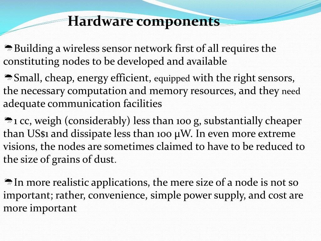
Hardware components • Building a wireless sensor network first of all requires the constituting nodes to be developed and available • Small, cheap, energy efficient, equipped with the right sensors, the necessary computation and memory resources, and they need adequate communication facilities • 1 cc, weigh (considerably) less than 100 g, substantially cheaper than US$1 and dissipate less than 100 μW. In even more extreme visions, the nodes are sometimes claimed to have to be reduced to the size of grains of dust. • In more realistic applications, the mere size of a node is not so important; rather, convenience, simple power supply, and cost are more important
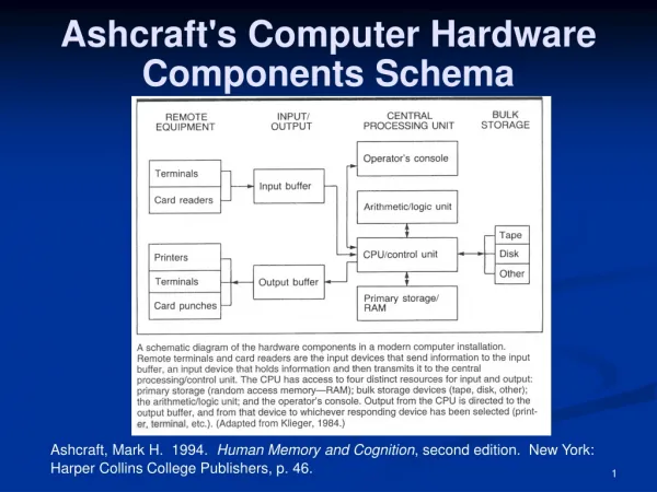
Figure Overview of main sensor node hardware components Controller : A controller to process all the relevant data, capable of executing arbitrary code. Memory : Some memory to store programs and intermediate data; usually, different types of memory are used for programs and data. Sensors and actuators : The actual interface to the physical world: devices that can observe or control physical parameters of the environment. Communication : Turning nodes into a network requires a device for sending and receiving information over a wired/wireless channel. Power supply : As usually no tethered power supply is available, some form of batteries are necessary to provide energy. Sometimes, some form of recharging by obtaining energy from the environment is available as well (e.g. solar cells)
Controller • Central Processing Unit (CPU) of the node. • It collects data from the sensors, processes this data, decides when and where to send it, receives data from other sensor nodes, and decides on the actuator’s behavior. • It has to execute various programs, ranging from time-critical signal processing and communication protocols to application programs • general-purpose processors, like those known from desktop computers but are highly overpowered, and their energy consumption is excessive; often have memory built in.
Microcontrollers: particularly suited to embedded systems are • flexibility in connecting with other devices (like sensors), • their instruction set amenable to time-critical signal processing, • require typically low power consumption • they are freely programmable and hence very flexible. • possibility to reduce their power consumption by going into sleep states where only parts of the controller are active; • FPGA (FIELD PROGRAMMABLE GATE ARRAYS) • can be reprogrammed (or rather reconfigured) “in the field” to adapt to a changing set of requirements; • however, this can take time and energy – • it is not practical to reprogram an FPGA at the same frequency as a microcontroller could change between different programs.
Application- Specific Integrated Circuits (ASICs) • An ASIC is a specialized processor, custom designed for a given application such as, for example, high-speed routers & switches • The typical trade-off here is loss of flexibility in return for a considerably better energy efficiency and performance. • where a microcontroller requires software development, ASICs provide the same functionality in hardware, resulting in potentially more costly hardware development • In future when the duties of the sensor node does not change over lifetime and no. of nodes is high ASIC will the best choice • At the current stage of WSN technology, however, the bigger flexibility and simpler usage of microcontrollers makes them the generally preferred solution.
Memory • Random Access Memory (RAM) to store intermediate sensor readings, packets from other nodes, and so on. • - While RAM is fast, its main disadvantage is that it loses its content if power supply is interrupted. • Program code can be stored in Read-Only Memory (ROM) or, more typically, in Electrically Erasable Programmable Read-Only Memory (EEPROM) or flash memory (the later being similar to EEPROM but allowing data to be erased or written in blocks instead of only a byte at a time). • Flash memory can also serve as intermediate storage of data in case RAM is insufficient or when the power supply of RAM should be shut down for some time. The long read and write access delays and high required energy should be taken into account • Correctly dimensioning memory sizes, especially RAM, can be crucial with respect to manufacturing costs and power consumption.
Communication device • The communication device is used to exchange data between individual nodes. • Choice of Transmission medium • Wired Communication & Wireless communication • -Radio frequency communication • - Non radio frequency Comm. • + optical communication • + ultrasound • - other media like magnetic inductance are only used in very specific cases. • Radio frequencies are more suitable to WSN applications. • - It provides relatively long range and high data rates, - acceptable error rates at reasonable energy expenditure, • - does not require line of sight between sender and receiver. • For a practical wireless, RF-based system, the carrier frequency has to be carefully chosen. WSN typically use communication frequencies between about 433 MHz and 2.4 GHz.
Optical • Using optical links between sensor nodes has the main advantage of very small energy per bit required for both generating and detecting optical light • simple LEDs are good examples for high-efficiency senders. • ADVANTAGES • -Required circuitry for an optical transceiver is also simpler • -device as a whole is smaller than the radio frequency counterpart • - Communication takes place concurrently with only negligible interference. • DISADVANTAGES • - communicating peers need to have a LOS connection • - optical communication is more strongly influenced by • weather conditions.
ULTRASOUND • Both RF and optical communication are suitable for open-air environments. • In some application scenarios, however, sensor nodes are used in environments where radio or optical communication is not applicable because these waves do not penetrate the surrounding medium. • One such medium is water, and an application scenario is the surveillance of marine ground floor erosion to help in the construction of offshore wind farms. • Sensors are deployed on the marine ground floor and have to communicate amongst themselves. • In underwater environment, ultrasound is an attractive communication medium as it travels relatively long distances at comparably low power. • Ultrasound is used in location systems as a secondary means of communication with a different propagation speed.
Transceivers • For actual communication, both a transmitter and a receiver are required in a sensor node. • The essential task is to convert a bit stream coming from a microcontroller (or a sequence of bytes or frames) and convert them to and from radio waves. • For practical purposes, it is usually convenient to use a device that combines these two tasks in a single entity. Such combined devices are called transceivers. • Usually, half-duplex operation is realized since transmitting and receiving at the same time on a wireless medium is impractical in most cases (the receiver would only hear the own transmitter anyway).
Transceiver tasks and characteristics Service to upper layer A receiver has to offer certain services to the upper layers, most notably to the Medium Access Control (MAC) layer. Sometimes, this service is packet oriented; sometimes, a transceiver only provides a byte interface or even only a bit interface to the microcontroller. In the other direction, incoming packets must be streamed into buffers accessible by the MAC protocol. Power consumption and energy efficiency The simplest interpretation of energy efficiency is the energy required to transmit and receive a single bit. Also, to be suitable for use in WSNs, transceivers should be switchable between different states, for example, active and sleeping. The idle power consumption in each of these states and during switching between them is very important – details are discussed in Section 2.2. Carrier frequency and multiple channels Transceivers are available for different carrier frequencies; evidently, it must match application requirements and regulatory restrictions. It is often useful if the transceiver provides several carrier frequencies (“channels”) to choose from, helping to alleviate some congestion problems in dense networks. Such channels or “subbands” are relevant, for example, for certain MAC protocols (FDMA or multichannel CSMA/ ALOHA techniques, see Chapter 5). Transceiver tasks and characteristics 1. Service to upper layer : A receiver has to offer certain services to the upper layers, most notably to the Medium Access Control (MAC) layer. Sometimes, this service is packet oriented; sometimes, a transceiver only provides a byte interface or even only a bit interface to the microcontroller. In the other direction, incoming packets must be streamed into buffers accessible by the MAC protocol. 2. Power consumption and energy efficiency: Energy efficiency is the energy required to transmit and receive a single bit. Also, to be suitable for use in WSNs, transceivers should be switchable between different states, for example, active and sleeping. The idle power consumption in each of these states and during switching between them is very important. 3. Carrier frequency and multiple channels: Transceivers are available for different carrier frequencies; must match application requirements and regulatory restrictions. Should alleviate congestion problems in dense networks.subbands- for certain MAC protocols (FDMA or multichannel CSMA/ALOHA techniques 4. State change times and energy: A transceiver can operate in different modes: sending or receiving, use different channels, or be in different power-safe states. In any case, the time and the energy required to change between two such states are important figures of merit.
5. Data rates: Carrier frequency and used bandwidth together with modulation and coding determine the gross data rate. - Typical values are a few tens of kilobits per second – considerably less than in broadband wireless communication, but usually sufficient for WSNs. - Different data rates can be achieved, for example, by using different modulations or changing the symbol rate. 6. Modulations: The transceivers typically support one or several of on/off-keying, ASK, FSK, or similar modulations. 7. Coding : Some transceivers allow various coding schemes to be selected. 8. Transmission power control: Some transceivers can directly provide control over the transmission power to be used; some require some external circuitry for that purpose. 9. Noise figure : NF =SNR(I) of the element/ SNR(O) of element -It describes the degradation of SNR due to the element’s operation and in dB: NF dB = SNRI dB − SNRO dB
10. Gain : The gain is the ratio of the output signal power to the input signal power and is typically given in dB. Amplifiers with high gain are desirable to achieve good energy efficiency. 11.Power efficiency The efficiency of the radio front end is given as the ratio of the radiated power to the overall power consumed by the front end; for a power amplifier, the efficiency describes the ratio of the output signal’s power to the power consumed by the overall power amplifier. 12. Receiver sensitivity : The receiver sensitivity (given in dBm) specifies the minimum signal power at the receiver needed to achieve a prescribed Eb/N0 or a prescribed bit/packet error rate. Better sensitivity levels extend the possible range of a system. 13. Range: The range is considered in absence of interference; it evidently depends on the -maximum transmission power, - antenna characteristics, - attenuation caused by the environment - which in turn depends on used carrier frequency, modulation/coding scheme - bit error rate that one is willing to accept at the receiver. -depends on the quality of the receiver, essentially captured by its sensitivity. Typical values ranges between a few meters and several hundreds of meters 14. Blocking performance:The blocking performance of a receiver is its achieved bit error rate in the presence of an interferer. 15. Out of band emission 16. Frequency stability 17. Voltage range
Transceiver operational states Transmit : transmit part of the transceiver is active and the antenna radiates energy. Receive: receive part is active. Idle : A transceiver that is ready to receive but is not currently receiving anything is said to be in an idle state. In this idle state, many parts of the receive circuitry are active, and others can be switched off. For example, in the synchronization circuitry, some elements of acquisition are active, while those concerned with tracking can be switched off and activated only when the acquisition has found something. Sleep: significant parts of the transceiver are switched off. sleep states differ in the amount of circuitry switched off and in the associated recovery times and startup energy .
Sensors • Sensors can be roughly categorized into three categories : • Passive, omnidirectional sensors :measures a physical quantity at the point of the sensor node without actually manipulating the environment by active probing – in this sense, they are passive. • - some of these sensors actually are self-powered in the sense that they obtain the energy they need from the environment – energy is only needed to amplify their analog signal. There is no notion of “direction” involved in these measurements. • -Typical examples for such sensors include thermometer, light sensors, vibration, microphones, humidity, mechanical stress or tension in materials, chemical sensors sensitive for given substances, smoke detectors, air pressure, and so on. • 2. Passive, narrow-beam sensors These sensors are passive as well, but have a well-defined notion of direction of measurement. A typical example is a camera, which can “take measurements” in a given direction, but has to be rotated if need be. • 3. Active sensors :This last group of sensors actively probes the environment, for example, a sonar or radar sensor or some types of seismic sensors, which generate shock waves by small explosions.
ACTUATORS • Actuators are just about as diverse as sensors, yet for the purposes of designing a WSN • all that a sensor node can do is to open or close a switch or a relay or to set a value in some way. • In a real network, however, care has to be taken to properly account for the idiosyncrasies of different actuators. • Also, it is good design practice in most embedded system applications to pair any actuator with a controlling sensor – following the principle to “never trust an actuator”
POWER SUPPLY OF SENSOR NODES • Energy scavenging • Some of the unconventional energy stores – fuel cells, micro heat engines, radioactivity • – convert energy from some stored, secondary form into electricity in a less direct and easy to use way than a normal battery would do. The entire energy supply is stored on the node itself – once the fuel supply is exhausted, the node fails. • To ensure truly long-lasting nodes and wireless sensor networks, such a limited energy store is unacceptable. Rather, energy from a node’s environment must be tapped into and made available to the node – energy scavenging should take place. • 1. Photovoltaics : solar cells can be used to power sensor nodes. The available power depends on whether nodes are used outdoors or indoors, and on time of day and whether for outdoor usage. Single cells achieve a fairly stable output voltage of about 0.6 V and resulting power is somewhere between 10 μW/cm2 indoors and 15 mW/cm2 outdoors. • 2. Temperature gradients: Differences in temperature can be directly converted to electrical energy. Theoretically, even small difference of, for example, 5 K can produce considerable power
3. Vibrations: One almost pervasive form of mechanical energy is vibrations: walls or windows in buildings are resonating with cars or trucks passing in the streets, machinery often has low frequency vibrations, ventilations also cause it etc., - Converting vibrations to electrical energy can be undertaken by various means, based on electromagnetic, electrostatic, or piezoelectric principles. - The available energy depends on both amplitude and frequency of the vibration and ranges from about 0.1 μW/cm3 up to 10, 000 μW/cm3 4. Pressure variations: variation of pressure can also be used as a power source as in piezoelectric generators. One well-known example is the inclusion of a piezoelectric generator in the heel of a shoe, to generate power as a human walks about. This device can produce, on average, 330 μW/cm2. 5. Flow of air/liquid: Another often-used power source is the flow of air or liquid in wind mills or turbines. The challenge here is again the miniaturization, but some of the work on millimeterscale MEMS gas turbines might be reusable.
Energy consumption of sensor nodes • energy supply for a sensor node is at a premium: batteries have small capacity, and recharging by energy scavenging is complicated and volatile. Hence, the energy consumption of a sensor node must be tightly controlled. • The main consumers of energy are the controller, the radio front ends, to some degree the memory, and, depending on the type, the sensors. • to reduce power consumption of these components comes from chip-level and lower technologies • “active”, “idle”, and “sleep”; Figure Energy savings and overheads for sleep modes