Download
1 / 42
420 likes | 566 Views
XMASS experiment. WIN05. 8 th June 2005. Takeda for the XMASS collaboration Kamioka Observatory, ICRR, University of Tokyo. Introduction R&D status using prototype detector Summary. 1. Introduction. Solar neutrino. What’s XMASS. Multi purpose low-background experiment with liq. Xe.

E N D
XMASS experiment WIN05 8th June 2005 • Takeda for the XMASS collaboration • Kamioka Observatory, ICRR, • University of Tokyo • Introduction • R&D status using prototype detector • Summary
1. Introduction Solar neutrino • What’s XMASS Multi purpose low-background experiment with liq. Xe • Xenon MASSive detector for solar neutrino (pp/7Be) • Xenon neutrino MASS detector (bb decay) • Xenon detector for Weakly Interacting MASSive Particles (DM search) Dark matter Double beta
Why liquid xenon • Large Z (=54) Self-shielding effect • Large photon yield (~42 photons/keV ~ NaI(Tl)) Low threshold • High density (~3 g/cm3) Compact detector (10 ton: sphere with diameter of ~2m) • Purification (distillation) • No long life radioactive isotope • Scintillation wavelength (175 nm, detected directly by PMT) • Relative high temperature (~165 K)
Key idea: self-shielding effect for low energy events Single phase liquid Xe External g ray from U/Th-chain Volume for shielding 23ton all volume 20cm wall cut 30cm wall cut (10ton FV) Fiducial volume Large self-shield effect BG normalized by mass PMTs 0 1MeV 2MeV 3MeV
Strategy of the scale-up 10 ton detector 800kg detector 100kg Prototype With light guide ~30cm ~80cm ~2.5m R&D Dark matter search We are now here Multipurpose detector (solar neutrino, bb …)
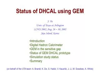
Trend of Dark matter (WIMPs) direct searches • Recoiled nuclei are mainly observed by 3 ways Scintillation NaI, Xe, CaF2, etc. Phonon Ionization Ge Ge, TeO2, Al2O3, LiF, etc Ge, Si • Taking two type of signals simultaneously is recent trend CDMS, EDELWEISS: phonon + ionization • g ray reduction owing to powerful particle ID • However, seems to be difficult to realize a large and uniform detector due to complicated technique
Super-K SNO KamLAND Strategy chosen by XMASS • Make large mass and uniform detector (with liq. Xe) • Reduce g ray BG by fiducial volume cut (self shielding) Same style as successful experiments of Super-K, SNO, KamLAND, etc.
800 kg detector Main purpose: Dark Matter search External g ray BG: 60cm, 346kg 40cm, 100kg Achieved pp & 7Be solar n ~80cm diameter Expected dark matter signal (assuming 10-42 cm2, Q.F.=0.2 50GeV / 100GeV,) • ~800-2” PMTs immersed into liq. Xe • 70% photo-coverage ~5 keVee threshold
Total 840 hex PMTs immersed into liq. Xe • 70% photo-coverage • Radius to inner face ~43cm Geometry design • A tentative design (not final one) 12 pentagons / pentakisdodecahedron This geometry has been coded in a Geant 4 based simulator
Hamamatsu R8778MOD(hex) • Hexagonal quartz window • Effective area: f50mm (min) • QE <~25 % (target) • Aiming for 1/10 lower background than R8778 5.8cm (edge to edge) 0.3cm (rim) c.f. R8778 U 1.8±0.2x10⁻² Bq Th 6.9±1.3x10⁻³ Bq 40K 1.4±0.2x10⁻¹ Bq 5.4cm • Prototype has been manufactured already • Now, being tested 12cm
Expected sensitivities XMASS FV 0.5 ton year Eth = 5 keVee~25 p.e., 3s discovery w/o any pulse shape info. 10-4 106 • Large improvements will be expected SI ~ 10-45 cm2 = 10-9 pb SD~ 10-39 cm2 = 10-3 pb 104 Edelweiss Al2O3 10-6 Tokyo LiF 102 Modane NaI Cross section to nucleon [pb] CRESST 1 UKDMC NaI 10-8 XMASS(Ann. Mod.) NAIAD 10-2 XMASS(Sepc.) 10-10 10-4 Plots except for XMASS: http://dmtools.berkeley.edu Gaitskell & Mandic
2. R&D status using prototype detector • Main purpose 100kg prototype • Confirmation of estimated 800 kg detector performance • Vertex and energy reconstruction by fitter • Miss fitting due to dead angle of the cubic detector (“wall effect”, will be explained later) can be removed with light guide • Self shielding power ~30 cm cube 3 kg fiducial With light guide version • BG study • Understandingof the source of BG • Measuring photon yield and its attenuation length
54 2-inch low BG PMTs Hamamatsu R8778 16% photo- coverage Liq. Xe (31cm)3 MgF2 window • 100 kg prototype detector In the Kamioka Mine (near the Super-K) 2,700 m.w.e. OFHC cubic chamber Gamma ray shield
4p shield with door 1.0m Rn free air (~3mBq/m3) 1.9m
Progress so far • 1st run (Dec. 2003) • Confirmed performances of vertex & energy reconstruction • Confirmed self shielding power for external g rays • Measured the internal background concentration • 2nd run (Aug. 2004) • Succeeded to reduce Kr from Xe by distillation • Photo electron yield is increased • Measured Rn concentration inside the shield • 3rd run (Mar. 2005) with light guide • Confirmed the miss fitting (only for the prototype detector) was removed • Now, BG data is under analysis
- m m n exp( ) å = Log( L ) Log( ) n ! PMT • Vertex and energy reconstruction Reconstruction is performed by PMT charge pattern (not timing) Reconstructed here Calculate PMT acceptances from various vertices by Monte Carlo. Vtx.: compare acceptance map F(x,y,z,i) Ene.: calc. from obs. p.e. & total accept. QADC L: likelihood F(x,y,z,i) m : x total p.e. S F(x,y,z,i) n: observed number of p.e . FADC Hit timing F(x,y,z,i): acceptance for i-th PMT (MC) VUV photon characteristics: Lemit=42ph/keV tabs=100cm tscat=30cm === Background event sample === QADC, FADC, and hit timing information are available for analysis
hole C hole A hole B DATA MC 1. Performance of the vertex reconstruction Collimated g ray source run from 3 holes (137Cs, 662keV) + + + C A B → Vertex reconstruction works well
All volume 20cm FV 10cm FV 2. Performance of the energy reconstruction Collimated g ray source run from center hole 137Cs, 662keV s=65keV@peak (s/E ~ 10%) Similar peak position in each fiducial. No position bias → Energy reconstruction works well
Demonstration of self shielding effect z position distribution of the collimated g ray source run γ → Data and MC agree well
Shelf shielding for real data and MC All volume All volume 20cm FV 20cm FV 10cm FV (3kg) 10cm FV (3kg) Aug. 04 run preliminary ~1.6Hz, 4 fold, triggered by ~0.4p.e. REAL DATA 3.9days livetime MC simulation Event rate (/kg/day/keV) 10-2/kg/day/keV Miss-reconstruction due to dead-angle region from PMTs. • Good agreement (< factor 2) • Self shielding effect can be seen clearly. • Very low background (10-2 /kg/day/keV@100-300 keV)
214Bi 214Po 210Pb a (7.7MeV) b (Q=3.3MeV) t1/2=164ms 208Po 212Bi 212Po a (8.8MeV) b (Q=2.3MeV) t1/2=299ns • Internal backgrounds in liq. Xe were measured Main sources in liq. Xe are Kr, U-chain and Th-chain • Kr =3.3±1.1 ppt (by mass spectrometer) → Achieved by distillation • U-chain =(33±7)x10-14 g/g (by prototype detector) • Th-chain< 23x10-14 g/g(90%CL) (by prototype detector) Delayed coincidence search (radiation equilibrium assumed) Delayed coincidence search (radiation equilibrium assumed)
Kr concentration in Xe • 85Kr makes BG in low enegy region Target = Xe 102 cpd/kg/keV Kr 0.1ppm 1 10-2 DM signal (10-6 pb, 50GeV, 100 GeV) 10-4 10-6 • Kr can easily mix with Xe because both Kr and Xe are rare gas 0 200 400 600 800 energy (keV) • Commercial Xe contains a few ppb Kr
Xe purification system • XMASS succeeds to reduce Kr concentration in Xe from ~3[ppb] to 3.3(±1.1)[ppt] with one cycle (~1/1000) • Processing speed : 0.6 kg / hour • Design factor : 1/1000 Kr / 1 pass • Purified Xe : Off gas = 99:1 Lower ~3m Raw Xe: ~3 ppb Kr (178K) Off gas Xe: 330±100 ppb Kr (measured) ~1% Purified Xe: 3.3±1.1 ppt Kr (measured) Higher ~99% Operation@2atm (180K) (preliminary)
Summary of BG measurement 1/100 Now (prototype detector) Goal (800kg detector) • g ray BG ~ 10-2 cpd/kg/keV 10-4 cpd/kg/keV → Increase volume for self shielding → Decrease radioactive impurities in PMTs (~1/10) • 238U = (33±7)×10-14 g/g 1×10-14 g/g → Remove by filter • 232Th < 23×10-14 g/g (90% C.L.) 2×10-14 g/g → Remove by filter (Only upper limit) • Kr = 3.3±1.1 ppt 1 ppt → Achieve by 2 purification pass 1/33 1/12 1/3 Very near to the target level!
Remaining problem: wall effect (only for the prototype detector) HIT HIT HIT HIT HIT ? MC If true vertex is used for fiducial volume cut 1 Dead angle 10-1 10-2 • Scintillation lights at the dead angle from PMTs give quite uniform 1 p.e. signal for PMTs, and this cause miss reconstruction as if the vertex is around the center of detector 1000 2000 3000 0 Energy (keV) No wall effect This effect does not occur with the sphere shape 800 kg detector
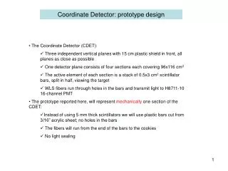
Active veto Fiducial PTFE light guide (UV reflection) 10cm 10cm 10cm • Prototype detector with light guide Purpose: remove the wall effect and understand the source of BG in the DM region 10X10X10cm3 (~3 kg Xe) 6 pieces
Light guide setup • Edging of PTFE surfaces 222Rn decays (210Pb b, 64 keV endpoint) implanted in PTFE surfaces might make the dominant BG α 222Rn air We edged the PTFE inside ~10μm PTFE 218Po α 214Pb α N.J.T. Smith et al., Phys. Lett. B 485 (2000) 9 Position distribution of 210Pb (in NaI) 210Pb Recoil process implants 30% of the original surface Rn decays 0 0.05 0.10 0.15 Z [mm] Implanted to ~0.1μm
1.0 Efficiency 0.8 0.6 0.4 0.2 0 80 100 20 60 0 40 Expected BG spectrum ・ MC simulation was done with GEANT3 BG spectrum Efficiency curve 1 PMT K 0.48p.e./keV PMT Th cpd/keV/kg PMT U Fast neutron BG (90% C.L. upper limit) 10-2 Signal window (10-15keV) 10-4 0 60 80 100 40 20 energy(keV) energy(keV) Efficiency~30% @10keV Expected BG~10-2cpd/keV/kg → Very low BG ~ 10-2 cpd/keV/kg @ <100keV
Result 1: comparing the data taken with and without light guide Collimated g ray source run from hole-B (137Cs, 662keV) Hole-B • with light guide • w/o light guide 10cm fiducial fiducial volume Counts Counts Energy [keV] Energy [keV] Reduce the events due to the wall effect
Result 2: Obtained energy spectrum outside the light guide Outside the light guide(Data) Outside light guide(MC) 10 10 Live time (3.3days) 1 1 events/keV/kg/day events/keV/kg/day 10-1 10-1 10-2 10-2 10-3 10-3 10-4 10-4 1000 2000 3000 0 1000 2000 3000 0 energy(keV) energy(keV) • Good agreement (< factor 2) • Trigger rate is same as the measurement witout guide (Aug. 2004)
3. Summary • XMASS experiment: Multi purpose low-background experiment with large mass liq. Xe • 800 kg detector: Designed for dark matter shearch mainly, and 102 improvement of sensitivity above existing experiments is expected • R&D with the 100 kg prototype detector Most of the performancesrequired for 800 kg detector are confirmed
XMASS collaboration • ICRR, Kamioka Y. Suzuki, M. Nakahata, Y. Itow, S. Moriyama, M. Shiozawa, Y. Takeuchi , M. Miura, Y. Koshio, K. Ishihara, K. Abe, A. Takeda, T. Namba, H. Ogawa, S. Fukuda, Y. Ashie, A. Minamino, R. Nambu, J. Hosaka, K. Taki, T. Iida, K. Ueshima • ICRR, RCNN T. Kajita, K. Kaneyuki • Saga Univ. H. Ohsumi, Y. Iimori, • Tokai Univ. K. Nishijima, T. Hashimoto, Y. Nakajima, Y. Sakurai • Gifu Univ. S. Tasaka • Waseda Univ. S. Suzuki, K. Kawasaki, J. Kikuchi, T. Doke, A. Ota • Yokohama National Univ. S. Nakamura, T.Fukuda, S. Oda, N. Kobayashi, A. Hashimoto • Miyagi Univ. of Education Y. Fukuda, T. Sato • Seoul National Univ. Soo-Bong Kim, In-Seok Kang • INR-Kiev Y. Zdesenko, O. Ponkratenko • UCI H. Sobel, M. Smy, M. Vagins, P.Cravens • Sejong univ.Y. Kim • Ewha Womans Univ. K. Lim • Indiana Univ. M. Ishitsuka
Electronics of light guide run (Mar. 2005) ADC Fan-out delay 400ns PMT Inner PMT×6 Sum Amp PMT ID sum OD sum ID x8 x8 PMT FADC(8ch/500MHz) 1μs Sum Amp Outer PMT×48 ID sum OD sum PMT Gate generator Gain : 8.25×10⁶ FADC(2ch/250MHz) 16μs Discri(VME) Discri(NIM)~1/4p.e.thres. ID ≧ 2hit Trigger module x8 OD ≧ 4hit
measurement • Data taking : 3/9 ~ 3/19, 2005 • Background run : 3.7days runtime, 3.3days livetime • Trigger rate 1.5Hz (inner 0.2Hz, outer 1.4Hz) • Calibration run : 137Cs / 60Co / 57Co / 133Ba source run ID hit event OD hit event TDC FADC ID sum
Background study Expected spectra in all volume • Outside of the shield 0.71 cm-2 s-1 (>500keV) • RI sources in PMTs 238U : 1.8×10⁻² Bq/PMT 232Th : 6.9×10⁻³ Bq/PMT 40K : 1.4×10⁻¹ Bq/PMT • 210Pb in the lead shield 250Bq/kg 1 cpd/kg/keV Outside of the shield 238U in PMTs 232Th in PMTs 10-1 40K in PMTs 210Pb in lead shield 10-2 2000 3000 1000 0 keV
Scintillation photons Liq. Xe • Low energy calibration source (1) X-ray D • Attenuation length of 20 keV x-ray in liq. Xe is short ~ 50 μm • The overall size of the source itself should be small not to block the scintillation photons • EC decaying nuclei preferable X-rays • Candidates : 71Ge(463d), 153Gd(263d), 103Pd(17d) Irradiate neutrons to natural Pd wire of 10 μm diameter 102Pd(n,γ) 103Pd EC decay of 103Pd produce 20 keV x-ray
Low energy calibration source (2) ☆ 125I(X-ray source) : 27.5 keV (59.9day) ☆ Temperature Range : -200 ~ +100 in Centigrade ☆ Overall source diameter < 20 mm ☆ Weak source ~ a few kBq Material A F= 10mm Liq. Xe 125I (1kBq) Electrodeposition Length 60mm 5mm Source position Coating Material B Thick=3mm
Plan of prototype detector ☆ Introduce RI source(103Pd, 125I,…) inside the chamber → Source driving system is ready → Detailed study of the energy and vertex fitter Motor Wire Low energy g source (103Pd, 125I,…) Position accuracy is within 1mm