Download
1 / 14
140 likes | 227 Views
Motivation. control of smart wheelchairs for people suffering from quadriplegia asks for suitable interface methods available approaches employ still functioning communication channels like direction of gaze computer vision [Canzler et al. 2004]

E N D
Motivation • control of smart wheelchairs for people suffering from quadriplegia asks for suitable interface methods • available approaches employ still functioning communication channels like • direction of gaze • computer vision [Canzler et al. 2004] • electro-oculographic potential (EOG) [Gips 1998, Yanco 1998] • voice • coarse qualitative route descriptions [Mandel et al. 2006] • head posture • ultrasonic sensors [Jaffe 1982, Ford 1995] • inertial measurement units (IMU) [Chen 2003] • brain computer interfaces (BCI) • dependent / independent BCIs [Vanacker ???, Millan 2006]
Preliminary Work: Human Robot Interfaces • interpretation of coarse qualitative route descriptions via the mapping of pairs of spatial relations and landmarks onto annotated route graphs along the blue path front-left of me
Prerequisite: Low Level Safety Layer • for each combination of (discretized) rotational velocity (w) and translational velocity (v) precompute virtual sensor vs(v,w) • at runtime vs(v,w) allows for fast collision detection within local obstacle map • safety layer intervenes by setting v and w to zero if obstacle is located within dangerous part of virtual sensor
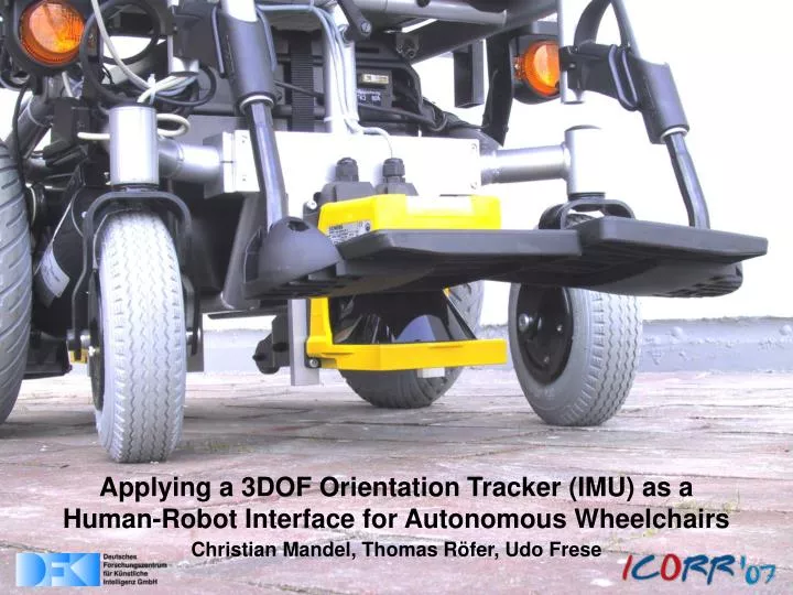
IMU based Head-Joystick: Basic Idea • three degrees of freedom orientation tracker, mounted at the back of the user`s head serves as suitable controlling equipment for an automated wheelchair • pitch-axis controls translational speed (v) roll-axis controls rotational speed (w) freeyaw-axis allows user to look around • proportional control: doubling the head`s pitch or roll angle doubles v or w respectively • safety layer monitors sorrounding obstacles and prevents from collisions
IMU based Head-Joystick: Calibration • calibration determines minimal and maximal pitch and roll deflection of a particular user`s head • dead zone around head`s point of rest defines interval of disregarded head movements
IMU based Head-Joystick: Static vs. Dynamic Roll Dead Zone • linear, quadratic, or cubic mapping of head posture onto translational and rotational velocity • static roll dead zone constrains rotational velocity to zero if the head`s roll angle is within a static intervall around the head`s rest position • dynamic roll dead zone increases with • increasing head`s pitch angle
standard joystick head-joystick head-joystick • 111 ms (static roll dead zone) (dynamic roll dead zone)Safety Layer Interventions445 ms 94 ms IMU based Head-Joystick: Experimental Evaluation
IMU based Path Planner Interface: Basic Idea • assumption 1: fixed height of user`s head • assumption 2: level surface • line of sight intersects with surface and determines target position • orientation in target position is given by obstacle situation • local path planner computes obstacle free paths to target pose by means of cubic Bezier curves
IMU based Path Planner Interface: Mapping Head Posture to Target Pose • line of sight is given by • assumed eyepoint e • head`s pitch angle • head`s yaw angle • problem of drifting delta between head`s yaw angle and odometry heading • orientation in target position t is given by tangent in t to actual distance grid, pointing away from wheelchair
IMU based Path Planner Interface: Cubic Bezier Curve Search Space • p0 and p1 predetermined by current pose and targeted pose • p1 and p2 span search space of possible solution paths • computational payload example: • 4400 curves • x 100 curve points • x 132 contour points • = O(58*106) collision tests • need for efficient collision test
IMU based Path Planner Interface: Proof of Concept • estimated path of an approximately 127m long test run triggered by head posture dependent target selection and simple voice commands
References • [Canzler 2004] „Person-adaptive facial feature analysis for an advanced wheelchair user-interface“ in Proceedings of the IEEE Intl. Conf. onMechatronics and Robotics, 2004 • [Gips 1998] „On building intelligence into eagleeyes“ in Lecture Notes in AI: Assistive Technology and Artificial Intelligence, 1998 • [Yanco 1998] „Wheelesley, a robotic wheelchair system: Indoor navigation and user interface“ in Lecture Notes in AI: Assistive Technology and Artificial Intelligence, 1998 • [Mandel 2006] „Robot navigation based on the mapping of coarse qualitative route descriptions to route graphs“ in Proceedings of the IEEE Intl. Conf. on Intelligent Robots and Systems, 2006 • [Jaffe 1982] „An ultrasonic head position interface for wheelchair control“ in Journal of Medical Systems, 1982 • [Ford 1995] „Ultrasonic head controller for powered wheelchairs“ in Journal of Rehabilitation Research and Development, 1995 • [Chen 2003] „A head oriented wheelchair for people with disabilities“ in Disability and Rehabilitation, 2003 • [Vanacker ???] „Context-based filtering for assisted brain-actuated wheelchair driving“, ??? • [Millan 2006] „Non-invasive brain-actuated control of a mobile robot by human eeg“ in IMIA Yearbook of Medical Informatics, 2006 Thank You!