Download
1 / 62
640 likes | 893 Views
Session 1. Session 5. Session 4. Session 3. Session 2. Session 6. Session 8. Session 7. Fiber Optic Grating Sensors and Applications. Blue Road Research. Criteria for a Successful Fiber Optic Sensor Application. Blue Road Research. Session 6, Page 1.

E N D
Session 1 Session 5 Session 4 Session 3 Session 2 Session 6 Session 8 Session 7 Fiber Optic Grating Sensors and Applications Blue Road Research
Criteria for a Successful Fiber Optic Sensor Application Blue Road Research Session 6, Page 1 • Meets and important application need • Is unique, superior solution • Is economically compelling
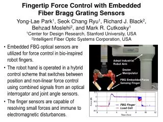
Fiber Grating Sensors Blue Road Research Session 6, Page 3 • Key parameters - strain and temperature • Competitive technology - electrical resistive strain gauges and thermocouples/low cost ($20) - well known, difficult to embed and successfully operate • Today - fiber gratings are high cost items ($200 each) being used to measure strain and temperature in embedded materials • The future - cost competitive with electrical strain gauges with options for 3 axis strain measurement, environmentally superior performance
Fiber Grating Sensor Prospects Blue Road Research Session 6, Page 4 • Fiber gratings are likely to drop into the $25 to $40 range for small quantity buys in two to three years enabling direct competitiveness with electrical strain gauges.
Fiber Grating - Holographic Method Laser beams Fiber Induced grating pattern Blue Road Research Session 6, Page 6
Fiber Grating - Phase Mask Method Laser beam Phase mask Fiber Induced grating pattern Blue Road Research Session 6, Page 7
Means to Write Fiber Gratings Blue Road Research Session 6, Page 8 • Long exposure side imaged interference pattern • United technology / operates to approximately 500 deg C • Good spectral characteristics /reflectance • Short pulse side imaged interference pattern • Naval Research Lab / operates to 800 deg C • Demonstrated manufacture during draw • First gratings low of quality
Means to Write Fiber Gratings(continued) Blue Road Research Session 6, Page 9 • Phase masks • Moderate temperature • Good performance • Canadian Communication Research Center • Line by line • Higher temperature to 800 deg C • Canadian Communication Research Center • Phase masks / bending fiber • Brown University / Bragg Technology • Wider bandwidth, good performance
Major Historical Milestones Blue Road Research Session 6, Page 10 • K.O. Hill, CRC 1978, discovery of photosensitivity. • Lam and Garside, McMaster U. 1981, observed photosensitivity as a two photon effect. • Meltz, Morey, and Glenn, UTRC 1989, side writing technique with UV laser. • Hill and Snitzer, CRC and Rutgers 1993, mask technique for writing fiber gratings. • LeMaire, AT&T 1993, Hydrogen loading. • Archambault, Reekie, Russell, Southampton U. 1993, single pulse, type 2 grating, and draw tower exposure. (Source - 3M Bragg Grating Technologies)
Bragg Grating Exposure Blue Road Research Session 6, Page 11 (Source - 3M Bragg Grating Technologies)
Photoinduced Index Change Blue Road Research Session 6, Page 12
0.1% Chirp, Peaks at 0.25 and 0.75L Blue Road Research Session 6, Page 13
Grating Reflection with 1nm Bandwidth and Reduced Sidelobes Blue Road Research Session 6, Page 14
Coupling to Cladding Modes with 4o Blaze Blue Road Research Session 6, Page 15
Wavelength-Selective Light Coupling from Fibers with Bragg Gratings Blue Road Research Session 6, Page 16
Bandpass Filter with Fiber Gratings in Michelson Arrangement Blue Road Research Session 6, Page 17
Transmission of Fiber Bragg Grating Pair as Fabry-Perot Interferometer Blue Road Research Session 6, Page 18
External Cavity Laser Diode Blue Road Research Session 6, Page 19 (Source - 3M Bragg Grating Technologies)
External Cavity Laser Diode Blue Road Research Session 6, Page 20 (Source - 3M Bragg Grating Technologies)
Temperature Relation for Grating Sensors Blue Road Research Session 6, Page 21 / = ( + ) T = expansion coefficient = 0.55x10⁻⁶oC-1 for silica = thermooptic coefficient for fiber core material = 8.31x10⁻⁶oC-1 estimated for GeO2 doping* / = 8.86x10⁻⁶T = 0.0073 nm/oC at 820 nm * From S. Tahahashi and S. Shibata, Journal of Non-Crystalline Solids 30(1979) 359-370
Strain Relation for Grating Sensors Blue Road Research Session 6, Page 22 / = (1 - pe) pe = photoelastic constant = (n2 / 2)[p12 - (p11 + p12)] = 0.22 for silica / = 0.78 = 6.4 nm / 1% at 820 nm
Fiber Grating Wavelength Shift Blue Road Research Session 6, Page 23 (Source - 3M Bragg Grating Technologies)
Reflectivity Over Test Period at 650 oC Blue Road Research Session 6, Page 24
Bandwidth Over Test Period at 650 oC Blue Road Research Session 6, Page 25
Transmission Plots Before and After High Temperature Exposure Blue Road Research Session 6, Page 26 (Source - 3M Bragg Grating Technologies)
Temperature and Strain Cycling Temperature Cycle Test Strain Cycle Test Blue Road Research Session 6, Page 27 • Use preannealed FBG • 4 hour cycles, 21 oC to 427oC • 512 cycles over 2048 hr.. • No change measured in FBG spectrum • Apply dynamic strain in tension load • Maximum strain 2500 microstrain • 1.4 million cycles • No change measured in FBG spectrum
Fiber Grating Demodulators Blue Road Research Session 6, Page 28 • Open loop versus closed loop • Open loop single grating approach requires broadband grating • Brown University is working on broadband chirped gratings • PZT stacks and designs for adequate modulation exist at modest voltages
Low Cost Approaches Blue Road Research Session 6, Page 29 • Overcoupled coupler • Miniature Mach-Zehnder • Fiber grating spectral filter
Overcoupled Beamsplitter Layout Light source Fiber grating Overcoupled beamsplitter Ratioed output Detectors Blue Road Research Session 6, Page 30
Overcoupled Coupler Issues Blue Road Research Session 6, Page 31 • Thermal drift more severe with higher sensitivity • Polarization mixing issues • Packaging of sensitive devices • very long overcoupled couplers are fragile
Miniature Mach-Zehnder Blue Road Research Session 6, Page 32 • More rugged than overcoupled coupler approach with comparable sensitivity • Superior thermal and polarization properties to overcoupled coupler • Smooth spectral profile • Needs further thermal and polarization improvements - close to ready
Grating Sensor with Fiber-Interferometric Wavelength Discriminator Blue Road Research Session 6, Page 33
Fiber Grating Spectral Filter Blue Road Research Session 6, Page 34 • Can be tailored to match desired dynamic range and sensitivity • Athermal package for operation over -40 to 80 oC (less than 0.1 nm drift) • Relatively polarization independent • Suitable for a demodulator with approximately 100 microstrain sensitivity and +/- 5000 microstrain range
Fiber Grating Spectral Filter Demodulator Light source Fiber grating Fiber grating spectral filter Beamsplitters Receivers Blue Road Research Session 6, Page 35
Chirped Fiber Grating Spectral Filter Blue Road Research Session 6, Page 36
1550 nm Grating Demodulation Kit Blue Road Research Session 6, Page 37 • 1550 nm ELED light source • (2) 3 dB beamsplitters • Chirped fiber grating filter • (2) receivers • Patch cords • FC connector cleaner • 1 single axis grating sensor • Data CD with manual • Optional DAQ card & software • Optional Carrying case
High Speed Grating Demodulators Blue Road Research Session 6, Page 38 • Stand-alone configuration • Three bandwidth options • 1kHz, 10 kHz, 2 MHz • Flexible design for varied applications • Integrated light source and spectral filters
Fiber Grating System Light source Fiber gratings 1 2 Detector Modulated reference fiber grating Blue Road Research Session 6, Page 39
Fiber Fabry-Perot Tunable Filters Mirrors PZT actuator Cavity length 20 microns for 50 nm FSR Air gap 1-2 microns Blue Road Research Session 6, Page 40
Fabry-Perot Detector/Fiber Silicon detector Fiber Capillary tube Silicon layer Silicon dioxide Bimorph actuator Blue Road Research Session 6, Page 41
Fiber Bragg Grating Sensor Array with Fiber Fabry-Perot Demodulator Blue Road Research Session 6, Page 42
Shift in FFP Control Voltage and Bragg Wavelength with Applied Strain to FBG Sensor Element Blue Road Research Session 6, Page 43
Bragg Grating Axial Strain and Temperature Sensor Blue Road Research Session 6, Page 44 • Measures T and 1 for surface mounted applications • Overlaid Bragg gratings at two wavelengths • 850 and 1300 nm • Output spectrum contains two peaks • b1 = f1(1,T) and b2 = f2(1,T)
Multi-Parameter Bragg Grating Blue Road Research Session 6, Page 45 • Two overlaid Bragg gratings created in birefringent fiber • 1, 2 • Birefringent fiber can transmit two orthogonal polarization modes • p,q • Reflected spectrum will contain four peaks • p1, q2, p2, q2 • Four peaks can be used to determine three axis of strain and temperature • 1, 2, 3, T
Bragg Grating in Birefringent Fiber q q p p p0 = 2d0np0 q0 = 2d0nq0 Blue Road Research Session 6, Page 46 • Two polarization modes with different values of n (np, nq) • Two distinct Bragg peaks
Response of Birefringent Fiber to Applied Strain and Temperature Blue Road Research Session 6, Page 47 • When the fiber is subjected to or T, will shift due to change in d (elongation) and n (stress-optic effect)
Response of Birefringent Fiber to Applied Strain and Temperature Blue Road Research Session 6, Page 48 • If we assume 23=0, the equations are linear in and T
3 Axis Strain and Temperature Dual overwritten fiber gratings Polarization preserving fiber axes Blue Road Research Session 6, Page 49
Two Overlaid Gratings in Birefringent Fiber Blue Road Research Session 6, Page 50 • If we add a second grating to the fiber at a different wavelength, we will obtain two additional peaks in the reflected spectrum • The response of these new peaks will be different due to the wavelength dependence of fiber properties (pij, etc.) • The response of the four peaks to strain and temperature can be expressed as:
Determining Three Axes of Strain and Temperature Blue Road Research Session 6, Page 51 • Provided K is well conditioned, we can determine the strains (1, 2, 3) and temperature (T) from the change in wavelength of the four peaks using: