Download
1 / 15
150 likes | 371 Views
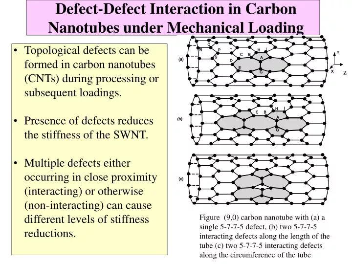
Defect-Defect Interaction in Carbon Nanotubes under Mechanical Loading. z. Topological defects can be formed in carbon nanotubes (CNTs) during processing or subsequent loadings. Presence of defects reduces the stiffness of the SWNT.

E N D
Defect-Defect Interaction in Carbon Nanotubes under Mechanical Loading z • Topological defects can be formed in carbon nanotubes (CNTs) during processing or subsequent loadings. • Presence of defects reduces the stiffness of the SWNT. • Multiple defects either occurring in close proximity (interacting) or otherwise (non-interacting) can cause different levels of stiffness reductions. Figure (9,0) carbon nanotube with (a) a single 5-7-7-5 defect, (b) two 5-7-7-5 interacting defects along the length of the tube (c) two 5-7-7-5 interacting defects along the circumference of the tube
Stress at atomic scale • Definition of stress at a point in continuum mechanics assumes that homogeneous state of stress exists in infinitesimal volume surrounding the point • In atomic simulation we need to identify a volume inside which all atoms have same stress • In this context different stresses- e.g. virial stress, atomic stress, Lutsko stress,Yip stresVirial Stres BDT (Atomic) Stresses
- fraction of the length of - bond lying inside the averaging volume Lutsko Stress • Based on concept of local stress in • statistical mechanics • used for inhomogeneous systems • Linear momentum conserved
Yip’s Stress Mechanical stress is calculated as sum of time rate of change of momentum flux and forces divided by area across particular surface of interest.
Strain calculation in nanotubes • Defect free nanotube mesh of hexagons • Each of these hexagons can be treated as containing four triangles • Strain calculated using displacements and derivatives shape functions in a local coordinate system formed by tangential (X) and radial (y) direction of centroid and tube axis • Area weighted averages of surrounding hexagons considered for strain at each atom • Similar procedure for pentagons and heptagons Updated Lagrangian scheme is used in MD simulations
CNT with 5-7-7-5 defect • Lutsko stress profile for (9,0) tube with type I defect shown below • Stress amplification observed in the defected region • This effect reduces with increasing applied strains • In (n,n) type of tubes there is a decrease in stress at the defect region
Strain profile • Longitudinal Strain increase also observed at defected region • Shear strain is zero in CNT without defect but a small value observed in defected regions • Angular distortion due to formation of pentagons & heptagons causes this
Elastic modulus of defect free CNT • -Defect free (9,0) nanotube • with periodic boundary • conditions • -Strains applied using • conjugate gradients energy • minimization • Longitudinal strain for the • tube is given by e =(L-Lo)/Lo, • where Lo and L is initial and • final length of the tube • Yip’s stress vs. longitudinal • strain curve Young’s (initial • tangent) modulus value of • 1.009TPa • Values in literature range • from 0.5 to 5.5 Tpa. Mostly • around 1Tpa Stress strain Curve for (9,0) tube with out defect.
Stiffness reduction for interacting defects placed along length • Two interacting defects placed along the length of the tube. • The stiffness reduction is maximum when the interacting defects are closer to each other • Stiffness loss reduces with increased spacing between two defects • when the defect spacing reaches a certain value (~30 separation units), the stiffness reduction remains constant and this length is define as the interacting distance. Variation of stiffness loss with spacing of two interacting defects, placed along the length of the tube. Separation unit is defined as l/ao , where separation distance is l and bond length ao,
Local Stress interaction for interacting defects placed along length • Lutsko’s stresses were computed locally over different segments(9 segments). • The Lutsko’s stress increases by 20% over defected region • When the defects are placed at a separation distance of 30 bond lengths, defect interaction does not occur • Wavelength of the peak curve is approximately 20 . • The peak value is reduces to 1.156 save from 1.2 save when defects are placed at 2.7 bond lengths and wavelength almost doubles to 40 when two defects juxtaposed Variation of longitudinal stress in CNT for different position of interacting defect at 8% applied strain.
Local Strain interaction for interacting defects placed along length • Local strains were computed in nine segments • The average strain in all cases is approximately 7.6 %, • The strain values near the defect increases to 9.2 % for the case where the defects are placed at 30-bond length away. • As the defects approaches each other, for e.g. the case with defects being 2.7 bond length away, the peak value of strain increases to 10.2 %indicating enhanced defect-defect interaction Variation of longitudinal strain along the CNT for different position of defects at 8% applied strain.
Stiffness reduction for interacting defects placed along circumference • The defects are placed along the circumference • Defect–defect interaction under tensile loading is very weak • Stresses/strains do not interact with the defect spacing • Irrespective of the defect spacing average % loss of stiffness is around 6% Variation of stiffness loss with spacing of two interacting defects, placed along the circumference of the tube.
Variation of stiffness with defect density • Loss of stiffness is considerably lower for the case of non-interacting defects when compared to that of interacting defects. • The loss of stiffness is gradual in both the case of non-interacting and interacting defects, when they are placed along the length of the nanotube • When increasing number of defects are placed along the circumference of the nanotube, the loss of stiffness is gradual up to a certain limit, and after that there is sharp loss of stiffness Variation of stiffness loss with increasing defect density
Variation of bond lengths and bond angles • Strains in CNTs manifest due to increase in bond lengths and change in bond angles. • Average bond length change is marginally higher in perfect region than in the defected region • Initial configuration of tube with defects deviates from perfect tube. • Change in Bond angle is considerable for tubes interacting defects. E.g. at 8% applied strain bond angle has increased from 11.58% (for single defect) to 16.11% (for two interacting defect) • Increased distortion in initial atomic configuration and increased bond angle change tends to induce much higher distortions resulting in higher reduction in stiffness (7% reduction for two close interacting defects; 5% reduction with single defect ) Variation of bond angle changes with respect to applied strain for the case of a tube with single defect and two closely interacting 5-7-7-5 defects
Summary • Topological defects reduces the stiffness of CNTs. • Reduction in stiffness depends on spacing and density of defects and interaction of defects. • Reduction in stiffness is more for a tube with interacting defect when compared to a tube with non-interacting tube. • Defect-defect interaction is effective with in certain critical separation distance, when two defects are placed along the length of the tube. • There is a gradual reduction in stiffness with increasing interacting defects placed along the length. • Sharp reduction in stiffness is observed for nanotube with increasing number of interacting defects placed along circumference.