Download
1 / 9
90 likes | 199 Views
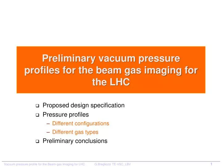
Preliminary vacuum pressure profiles for the beam gas imaging for the LHC. Proposed design specification Pressure profiles D ifferent configurations Different gas types Preliminary conclusions. Proposed design for the BGV for LHC. From M. Ferro- Luzzi. Required densities.

E N D
Preliminary vacuum pressure profiles for the beam gas imaging for the LHC Proposed design specification Pressure profiles Different configurations Different gas types Preliminary conclusions
Proposed design for the BGV for LHC From M. Ferro- Luzzi
Required densities • Densities (averaged over 1m) that would be needed for the BGV to work adequately for some representative gas types. Notes: since we only simulated H, O and Xe, we did this: * A and Fgoodfor CO2approximated by O3 #Fgoodfor Ne assumed same as for O (should be slightly better) • Can estimate performance of any other gas by estimating the Fgoodfrom the gas with the closest A and by scaling the density with A2/3(larger A, smaller density needed). • Reminder 1: is the molecular density, while the rate scales with the number of nuclei per cm3! • Reminder 2: what really counts is the target thickness (integrated along the useful z range) From M. Ferro- Luzzi
First Proposed Vacuum Layout Case of the BGV installed in 1 beam pipe For integration reasons the total length of the installed system is fixed to 7 m 8 cm NEG NEG Cartridges or Ion pumps 1 m 2 m Transition 8 cm - : 4 cm NEG 4 cm NEG Gas Injection 7 m
Summary with required pressure at 293K Q H2: 5E-5 mbar∙l/s Q CO: 1E-5 mbar∙l/s Q CO2: 3E-6 mbar∙l/s Q Ne: 2.5E-6 mbar∙l/s Q Ar: 5E-7 mbar∙l/s No pumping at the extremities 7 m Ion pump Ion pump NEG + Cartridges NEG + Cartridges
NEG Saturation consideration for CO and CO2 Sorption capacity for D400: 0.5 mbarl for CO and CO2 Sorption capacity for MK5: 8 mbarl for CO and CO2
Other possible configuration: Differential pumping NOBLE GASES 4 x Ion Pump 4 x Ion Pump 25 cm 8 cm 25 cm 8 cm 25 cm 8 cm 25 cm 8 cm Added two new area with smaller diameter: differential pumping 2) Added a new bigger dome with flanges for the integration of ion pumps 2 m 50 cm 1 m 25 cm 4 cm 25 cm 4 cm 25 cm 4 cm 25 cm 4 cm
Other possible BGV design 1 m 1 m 1 m 2 m 50 cm Bigger tube extremities 2 m 50 cm 1 m 1 m Conical 4m 50 cm Cylindrical