Download
1 / 46
460 likes | 596 Views
Optical Neural System Imaging Survey. November 15, 1999 Andreas G. Nowatzyk. Outline. Background and Motivation System Overview Backscatter Imager Fluorescent Imager Microtome Staining Unit Computational Aspects Summary. Context. Enabling technologies

E N D
Optical Neural System Imaging Survey November 15, 1999Andreas G. Nowatzyk
Outline • Background and Motivation • System Overview • Backscatter Imager • Fluorescent Imager • Microtome • Staining Unit • Computational Aspects • Summary
Context • Enabling technologies • Moore’s Law: Billions of Billions of cycles • Interconnect networks: Multi-Gbytes/s I/O • Optics: confocal microscopy, lasers • Biochemistry: selective staining • Computer science: Image processing • Mechanics: Chip fabrication technologies • Interdisciplinary research: Combining all these new tools to open up new research areas
Ultimate Goal: Scan a Mouse in 3D • Eventually, reverse engineer a mouse brain, including the entire rodent nervous system
Computational Challenge • 2 x 2 x 4 cm3 specimen volume • 0.2 mm resolution • = 100,000 x 100,000 x 200,000 voxels • 6 x 12 bit per voxel • 16,763,806 Gbytes of raw data • 200:1 compression (lossy) • => 1700 tapes (8mm, 50Gbytes/tape)
Computational Challenge • 20 Msamples/s per channel (12 bits each) • 6 x 64 channels • ~50% scan duty cycle • 2x for complex phase sensing • = 11,520 Mbytes/s average data rate
System Overview Basic approach, instrument architecture, and computing infrastructure
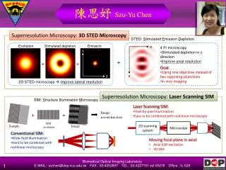
Functional Imaging • Selective labeling with Fluorescent Dyes • Genetically engineered Labels (GFP) VS.
Basic Approach • Use of light microscopy plus selective functional imaging • Five step process • Bulk imaging into freshly cut sample • Mechanical sectioning via integrated microtome • Automated, continuous staining • Functional, fluorescent imaging • Data fusion, compression and archival storage
Intensity Confocal Light Microscopy • Using one objective lens twice • Point-spread function squared
Backscatter Imager CarrierTape Transfer Unit Microtom Specimen Holder Staining Unit Fluorescent Imager Instrument Overview
Backscatter Imager Optical system, mechanical components, scan path
Design Objectives • Need to maximize throughput • Maximize practical resolution • Optical sectioning into the exposed sample surface
XZ Detection Function High NA (0.9) objective with pinhole detector PMT
XZ Detection Function Confocal illumination PMT
XZ Detection Function Michelson interferometer PMT
RF w-e w+e Acousto-Optical Modulator • Exploit Doppler shift to split laser into two components with differing frequency
XZ Detection Function Heterodyne detection X PMT f w-e w+e
Heterodyne Detection • Elimination of black-level drift through AC-coupled amplifiers • Contrast independent of reference beam intensity (within dynamic range of detector) • Optical phase transferred to electrical domain • Simultaneous capture of phase and magnitude • Enables wave-front reconstruction / holography
Solid State Detector • Better quantum efficiency (~ 85 vs 30 %) • Better dynamic range (> 120 db)
Backscatter Imager Summary • Optimized for single purpose • less relay optic, no eye piece, no turret, etc. • Scan system optimized for bulk operation • Heterodyne detection for improved Z-axis resolution (full sampling of the optical phase) • Multiple wavelengths • Requires computer controlled alignment
Fluorescent Imager Optical system, mechanical components, coherent detection
Design Objectives • Need to match throughput of backscatter imager • Film based input media, accessible from both sides with symmetric, optical properties • Support for optical sectioning
Problems • Dye saturation • Signal to noise ratio • Incoherent signal • Need to maximize light gathering ability and quantum efficiency of detector
Scan System • Sorry, the few slides were removed due to pending (but incomplete) patent applications
Microtom Functions, mechanical components
Design Objectives • Integrated with optical system • Fully automatic • Precise control of cutting plane and related parameters
Transferring fragile Objects to Film • Microtom with stationary knife • Floating pick-up • Match surface velocity to cutting speed • Minimize surface tension • Electrostatic transfer
Microscope Environment • -20 to -30 degree C, controlled operating temperature • dust free, controlled flow, dry nitrogen atmosphere • vibration isolation • issue: sublimation (prevent by index matching fluid)
Mechanical components • Linear air bearings • Voice-coil motor direct drive • Laser interferometer position sensing with 10nm resolution • Piezo-actuators for knife positioning
Staining Unit Outline, Challenges
Film as Sample Slice Carrier • Candidate: DuPont Cronar 410 polyester flim, gelatin coated, 100mm • Need to maintain sample adhesion during stating process • Optically clear, substitute for cover-slips (need to be witting correction range) • Chemically inert
Continuous Staining Process • Tight control of process parameters (temperature, flow rate, chemical concentrations, etc.) • Clean-room environment: dust-free, high purity, no manual steps • Uniform, predictable distortions
Computational Aspects Where does all the money go?
Computational Infrastructure • Instrument control • Front-end signal processing
Control System Overview • Linux based • 3 Functional Blocks: • System Controler • Signal Processing • File system / Database
Image processing • Deconvolution (CAT scan, MRI) • Super-Resolution [Cheeseman et al] • 3D reconstruction • Image fusion • 3D Compression
Circuit Extraction Algorithm • Linear scan of the data set • Connectivity function integrated with Bayesian super-resolution algorithm
Summary of Instrument Capabilities • 6 band (3 backscatter + 3 fluorescent labeled) confocal microscope • 0.2mm (or better) 3D resolution • Integrated sectioning and staining • Image acquisition and processing speed sufficient for large volume scanning
Summary • Large scale, high resolution scanning of biological specimen will become practical • Automated tracing of neurological systems is conceivable • Provides a clear, long term research focus • Significant Research potential • Intermediate, practical spin-off potential